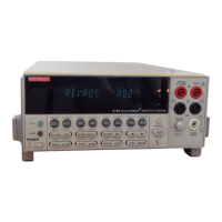
2-4 Model 2790 SourceMeter
®
Switch System User’s Manual
I-source – channels 21, 22, 24, and 27
The programmable I-source (0 to 50mA) is used as the test current to measure low resis-
tance (inflator bridgewires and shunt bars).
• The I-source is designated as channel 27.
• Opening channel 22 selects the I-source.
• Closing channel 21 connects the I-source.
• Closing channel 24 connects the dry circuit clamp for the shunt bar test (20mV,
1mA limit).
NOTE “Ohms specification calculations” in Appendix A explains how to determine the
accuracy specification for source levels not specified in the “7751/7752/7753
Source/Switch Module Specifications” sheet.
V-source and I/V amplifier (7751/7753 only) – channels 21, 22, 23, 28
The programmable voltage source (50 to 500V) and I/V amplifier are used to measure
high resistance (insulation resistance of an inflator).
• The V-source is designated as channel 28.
• Closing channel 22 selects the V-source.
• Closing channel 21 connects the V-source.
• Closing channel 23 connects the I/V amplifier.
WARNING Do not connect V-source Hi to earth ground. The 7751/7752/7753 mod-
ule uses a floating ground. This floating ground is not connected to
safety earth ground. Not only will it create a shock hazard by floating
up to 500V, it will also effectively connect a 1nF capacitor across the
V-source, providing energy storage that could ignite an airbag under
fault conditions.
NOTE “Ohms specification calculations” in Appendix A explains how to determine the
accuracy specification for source levels not specified in the “7751/7752/7753
Source/Switch Module Specifications” sheet.
Cable discharge (7751/7753 only) – channel 20
A cable discharge circuit is used to dissipate charge build-up on the inputs to prevent acci-
dental ignition of the inflator. For details, see “Cable discharge circuit”.
• Closing channel 20 discharges voltage on the input channels.

 Loading...