Model 2790 SourceMeter
®
Switch System User’s Manual 5-29
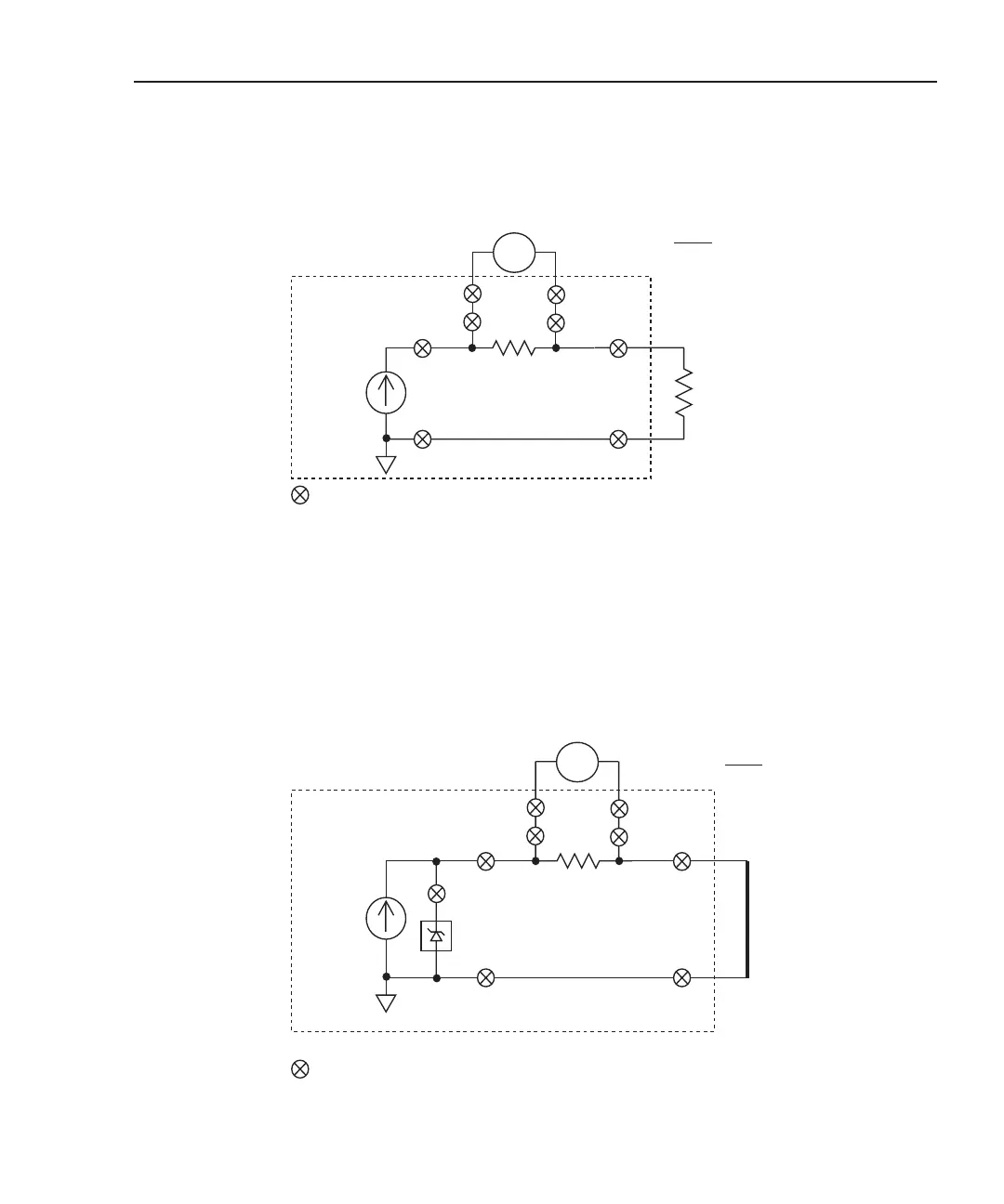
Figure 5-13
I-source readback circuit
21
21
1Ω
Shunt Bar
Under
Test
= Closed channel switch
21
21
1 or 4*
1Ω
2790 DMM
v
Input HI
Input LO
25
25
= Closed channel switch
Bridgewire
Under
Test
I
RB =
V
MEAS
1Ω
2 or 5*
Test assumptions:
To test inflator connected to Bank 1, close channels 1 and 2.
To test inflator connected to Bank 2, close channels 4 and 5.
A) Test circuit for current source readback (bridgewire)
B) Test circuit for current source readback (shunt bar)
Test assumption: Shunt bar connected to Bank 1
18
18
I
SOURCE
*
* Ch 22 open = I-source selected
2790 DMM
v
Input HI
Input LO
25
25
IRB =
V
MEAS
1Ω
18
18
I
SOURCE
*
* Ch 22 open = I-source selected
NOTE Each channel, except channel 24, is a 2-pole switch. Therefore,
when a 2-pole channel is closed, two switches close. Channel 24
is a 1-pole switch (see schematic in Figure 2-1).
Open switches not used in the test circuit are not shown.
20mV
Dry Ckt
24
Keithley 7751,
7752, or 7753
Keithley 7751,
7752, or 7753
1 or 4*
2 or 5*
* Channels 4 and 5 closed for applications with two shunt bars