Model 2790 SourceMeter
®
Switch System User’s Manual 5-25
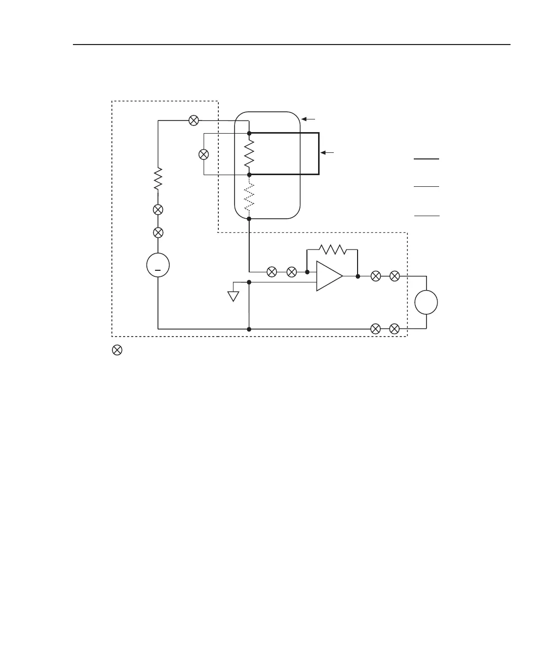
Figure 5-12
Test circuit – HIPOT
V
SOURCE
(7751/
7753)
Leakage
Under
Test
(RHIPOT)
+
RF
I/V Amplifier
(7751/7753)
22
1 or 4*
8
+
–
23
16
16
Inflator
3 and 6*
= Closed channel switch
Test assumptions:
To test a single inflator connected to Bank 1, close channels 1 and 3.
Closing channel 3 connects an internal, built-in shunt across the bridgewire.
To test a dual inflator connected to Banks 1 and 2, close channels 3, 4, and 6.
Closing channels 3 and 6 connects internal, built-in shunts across the two
bridgewires.
*
2790 DMM
v
Input HI
Input LO
21
Bridgewire
Inflator
Housing
RHIPOT = –
V
SOUR
VMEAS
x RF
= –
500V
V
MEAS
500V
18
18
Selects
V-source
Shunt
Bar
Internal
shunts
NOTE Each channel (except channel 23) is a 2-pole switch. Therefore, when
a 2-pole channel is closed, two switches close. Channel 23 is a 1-pole
switch (see schematic in Figure 2-1).
Open switches not used in the test circuit are not shown.
1Ω
Keithley 7751/7753
x 200kΩ (7751)
= –
500V
V
MEAS
x 20kΩ (7753)
200kΩ (7751), 20kΩ (7753)