5-14 Model 2790 SourceMeter
®
Switch System User’s Manual
Bridgewire tests
NOTE The interlock of the 7751/7752/7753 must be enabled to use the I-source.
Figure 5-6 shows how interlock is enabled.
Test circuit
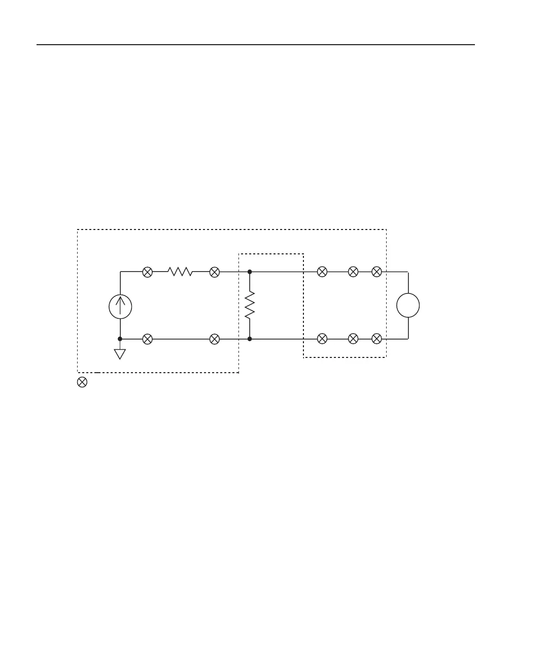
The circuit for an inflator bridgewire test is shown in Figure 5-8.
Figure 5-8
Test circuit – bridgewire tests
2790 DMM
v
Input HI
Input LO
17 18
18
21
21
1 or 4*
2 or 5*
Bridgewire
Under
Test
1Ω
= Closed channel switch
* Test assumptions:
To test bridgewire connected to Bank 1, close input channels 1 and 2.
To test bridgewire connected to Bank 2, close input channels 4 and 5.
17
ISOURCE*
* Ch 22 open = I-source selected
1 or 4*
2 or 5*
NOTE Each channel is a 2-pole switch. Therefore, when a channel
is closed, two switches close (see schematic in Figure 2-1).
Keithley 7751, 7752, or 7753