Model 2790 SourceMeter
®
Switch System User’s Manual 5-5
Test signal connections
There are four main test connection drawings (Figures 5-2, 5-3, 5-4, and 5-5), but you only
need to use the one that applies to your test system. Select the drawing that best suits your
needs and disregard the other three.
NOTE All the test circuits and procedures in this section assume that the inflator is con-
nected to the 7751/7752/7753 module as shown in Figure 5-2 through
Figure 5-5.
Single stage inflator test connections:
• Figure 5-2 — Use this connection scheme if using a Keithley 7752 module. It can
also be used for the 7751 or 7753 module if not performing the HIPOT test.
• Figure 5-3 — Use this connection scheme if using a Keithley 7751 or 7753 mod-
ule. It includes the connections for the HIPOT test.
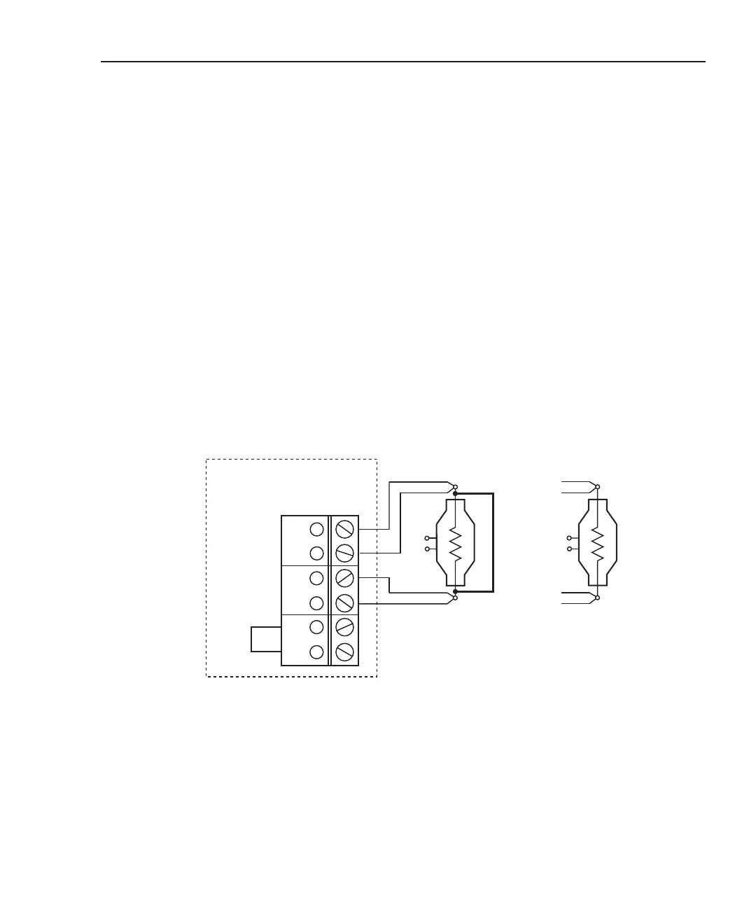
Figure 5-2
Test connections – shunt bar and bridgewire testing – single stage inflator
Single Stage Inflator
SRC HI
SEN HI
SRC LO
SEN LO
A1
B1
Ch 1
Ch 2
Bank 1
J101
Shunt
Bar
B) Bridgewire TestingA) Shunt Bar Testing
Keithley 7751, 7752, or 7753