SECTION 6
Theory of Operation
8.1 INTRODUCTION
This section contains electronic operating theory for the
various circuits within the Model 4%/4S7. The overall
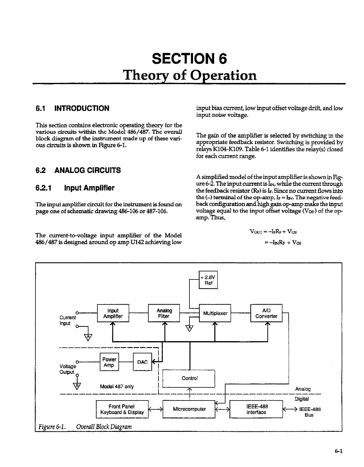
block diagram of the instrument made up of these vari-
ous circuits is shown in Figure 61.
8.2 ANALOG CIRCUITS
8.2.1 Input Amplifier
The input amplifier circuit for the instrument is found on
page one of schematic drawing 486-106 or 487-106.
input bias current, low input offset voltage drift, and low
input noise voltage.
The gain of the amplifier is seiected by switching in the
appropriate feedback resistor. Switching is provided by
relays KlWK109. Table 6-1 identifies the relay(s) closed
for each current range.
A simplified model of the input amplifier is shown in Fig-
ure
6-2.
The input current is IIN, while the current
through
the feedback resistor (IL) is k. Since no current flows into
the (-) terminal of the opamp, k = IN The negative feed-
back configuration and high gain op-amp make the input
voltage equal to the input offset voltage (VW) of the op-
amp. Thus,
The current-t-voltage input amplifier of the Model
486/487
is designed around op amp U142 achieving low
VOUT = -l&F + VOY
=-II?.& +vos
Figure 6-I. Omrulf BZock Diagram