SECTION 3
Front Panel Operation
3.16.4 Electrostatic interference
Electrostatic interference occurs when an electrically
charged object is brought near an uncharged object, thus
inducing a charge on the previously uncharged object.
Usually, the effects of such electrostatic action are not
noticeable because low impedance levels allow the
induced charge to dissipate quickly. However, high
impedance levels of many measurements do not allow
these charges to decay rapidly, and erroneous or unsta-
ble readings may be caused in the following ways:
1. DC electrostatic elds can cause undetected errors
or noise in the reading.
2. AC electrostatic elds can cause errors by driving
the ampli er into saturation, or through recti ca-
tion that produces dc errors.
Electrostatic interference is rst recognizable when
hand or body movements near the experiment cause
uctoations in the reading. Pick up from ac elds can
also be detected by observing the output on an oscillo-
scope. Line frequency signals on the output are an indi-
cation that electrostatic interference is present.
Means of minimizing electrostatic interference include:
1. Shielding. Possibilities include; a shielded room, a
shielded booth, shielding the sensitive circuit (test
xture), and using shielded cable. The shield
should always be connected to a solid connector
that is connected to signal low. Note, however, that
shielding can increase capacitance, possibly
slowing down response time.
2. Reduction of electrostatic elds. Moving power
lines or other sources away from the experiment
reduces the amount of electrostatic interference
seen.
3.16.5 Thermal EMFs
Thermal EMFs are small electric potentials generated by
differences in temperature at the junction of two dissim-
ilar metals. Low thermal connections should be used
whenever thermal EMFs are known to be a problem.
Crimped copper to copper connections can be used to
minimize these effects.
3.16.6 Electromagnetic Interference (EMI)
The electromagnetic interference characteristics of the
Model 486 Picoammeter and Model 487 I’icoammeter/
Voltage Source comply with the electromagnetic com-
patibility (EMC) requirements of the European Union
(EU) directives as denoted by the CE mark. However, it
is still possible for sensitive measurements to be affected
by external sources. In these instances, special precau-
tions may be required in the test setup.
Sources of EM1 include:
l
Radio and TV broadcast transmitters.
l
Communications transmitters, including cellular
phones and handheld radios.
l
Devices incorporating microprocessors and high-
speed digital circuits.
l
Impulse sources as in the case of arcing in high-
voltage environments.
The instrument, measurement leads, and other cables
should be kept as far away as possible from any EMI
sources. Additional shielding of the test xture, signal
leads, sources, and measuring instruments will often
reduce EMI to an acceptable level. In extreme cases, a
specially constructed screen room may be required to
suf ciently attenuate the troublesome signal.
Many instruments, including the Models 486/487,
incorporate internal ltering that may help reduce EM1
effects in some situations. Increasing the programmed
lter rise time will often help to reduce EMI. In some
cases, additional external ltering may be required.
Keep in mind, however, that ltering or increased rise
time may have detrimental effects on the desired signal.
3.16.7 Ground Loops
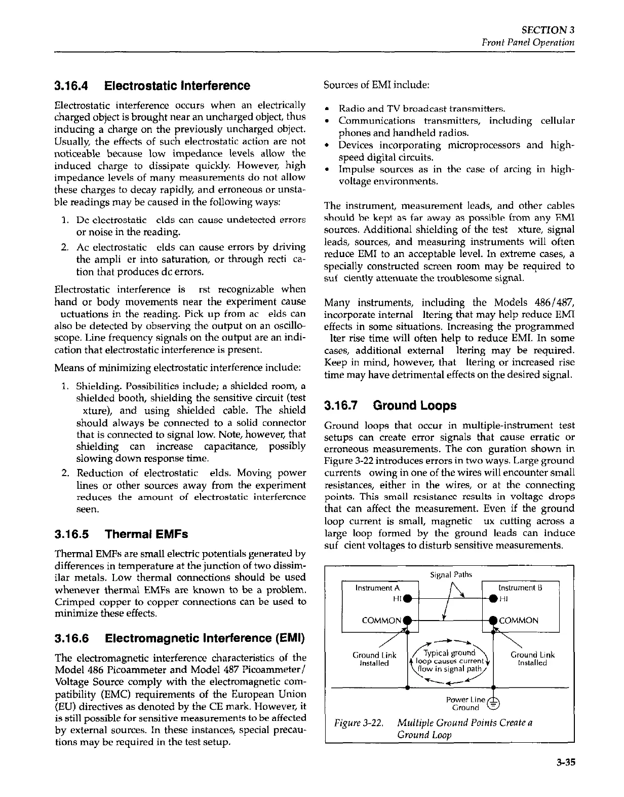
Ground loops that occur in multiple-instrument test
setups can create error signals that cause erratic or
erroneous measurements. The con goration shown in
Figure 3-22 introduces errors in two ways. Large ground
currents owing in one of the wires will encounter small
resistances, either in the wires, or at the connecting
points. This small resistance results in voltage drops
that can affect the measurement. Even if the ground
loop current is small, magnetic ux cutting across a
large loop formed by the ground leads can induce
suf cient voltages to disturb sensitive measurements.