SECWON 7
Maintenance
4. Any printed circuit board into which the device is to
be inserted must also be grounded to the bench or ta-
ble.
5. Use only anti-static type solder sucker.
6. Use only grounded tip solder irons.
7. Once the device is installed in the PC board, it is nor-
mally adequately protected, and normal handling
can resume.
7.7 TROUBLESHOOTING
The troubleshooting information contained in this sec-
tion is intended for use by qualified personnel having a
basic understanding of analog and digital circuitry. The
individual should also be experienced at using typical
test equipment as well as ordinary troubleshooting pro-
cedures. The information here has been written to assist
in isolating a defective circuit or circuit section. Isolation
of a specific component is left to the technician. Note that
schematic diagrams and component location drawings,
which are an essential aid to troubleshooting are in-
cluded in Section 8.
Before starting to troubleshoot the instrument, it is rec-
ommended that the theory of operation (Se&on 6) be
studied to familiarize yourself with some of the basic cir-
cuit principles.
7.7.1 Recommended Troubleshootlng
Equipment
Success in troubleshooting complex equipment like the
Model 486/487 depends not only on the skiU of the tech-
nician, but relies on the use of accurate, reliable test
equipment. Table 7-4 lists the equipment recommended
for troubleshooting the Model 486/487. Other equip-
ment, such as logic analyzers and capacitance checkers,
could also be helpful.
7.7.2 Self-Test
The self-test performs tests on the front panel LEDs, as
welI as the RAM and ROM ICs within the instrument.
Perform the self-test as follows:
1. Keeppressingand reIeasingMENUuntil thefollow-
ing message is displayed:
SELFTEST NO
7-12
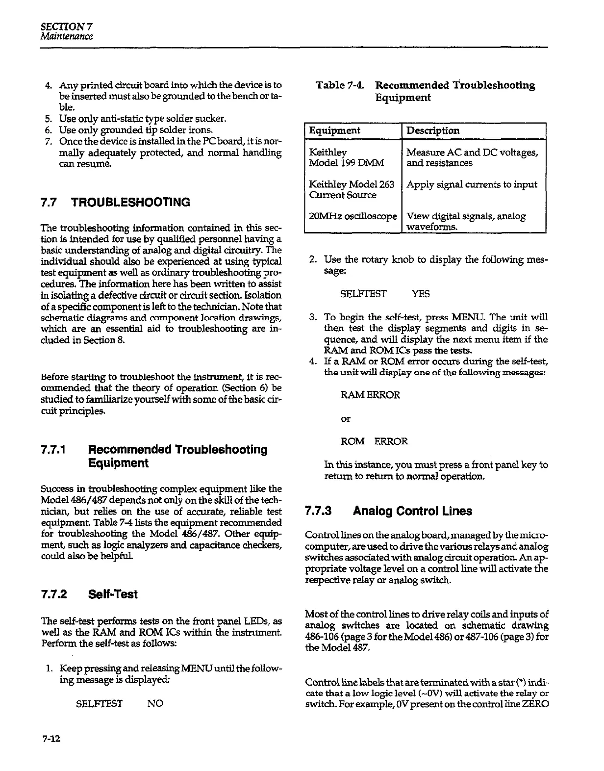
Table 7-4. Recommended Troubleshooting
Equipment
Equipment
Keithley
Model 199 DMM
KeithIey Model 263
Current Source
ZOMHZ oscilloscope
Description
Measure AC and DC voltages,
and resistances
Apply signal currents to input
View digital signals, analog
waveforms.
2. Use the rotary knob to display the following mes-
sage:
SELFIEST YES
3. To begin the self-test, press MENU. The unit will
then test the display segments and digits in se-
quence, and will display the next menu item if the
RAM and ROM ICs pass the tests.
4. If a RAM or ROM error occurs during the self-test,
the unit wiU display one of the following
messages:
RAMERROR
ROM ERROR
In this instance, you must press a front panel key to
reh.un to return to normal operation.
7.7.3
Analog Control Lines
Controllinesontheanalogb~d,managedbythemicro-
computer, are used to drive the various relays and analog
switches associated with analog circuit operation. An ap-
propriate voltage level on a control line wilI activate the
respective relay or anslog switch.
Most of the control lines to drive relay coils and inputs of
analog switches are located on schematic drawing
486-106 (page 3 for the Model 486) or 487-106 (page 3) for
the Model 487.
Controllinelabels that are terminated with a star (*) indi-
cate that a low logic level (-OV) will activate the relay or
switch. For example, OV present on the control line ZERO