SECTION 4
IEEE-488 Reference
4.2.6
G - Data Format
Purpose
Format
Default
Description
Control the format of output data that is transmitted over the bus.
Gn
GO ASCII readings with prefix
Gl ASCII readings without prefix
G2 ASCII readings and buffer location with prefix
G3 ASCII readings and buffer location without prefix
G4 Binary readings - IEEE Std 754 single-precision, bytes reversed for Intel CPLJs.
G5 Binary readings-IEEE Std 734 single-precision, bytes in normal order for Motorola U’Us.
G6 Binary readings - counts and exponent, bytes reversed for Intel CPUs.
G7 Bixwy readings-counts and exponent, bytes in normal order for Motorola CRJs.
Upon power-up, or after receiving a DCL or SDC command, the instrument will return to the
data format that was saved as the default condition.
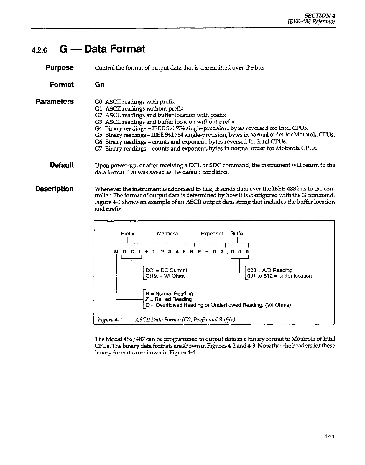
Whenever the instrument is addressed to talk, it sends data over the IEEE-488 bus to the con-
troller. The format of output data is determined by how it is configured with the G command.
Figure 4-1 shows an example of an ASCII output data string that indudes the buffer location
and prefix.
I
Prefix Mantissa Exponent Suffix
r--hA4-l~
NDCl~1.23456Ek.03.000
= Nonal Reading
2 = Rel’ ed Reading
= Overflowed Reading or Underflowed Reading, (V/I Ohms)
Figure 41. ASCIIDatnFonnat (G2;Prefxand Suffix
The Model 486/487 can be programmed to output data in a binary format to
Motorola or Intel
CPUs. The binary data formats are shown in Figures 42 and 43. Note that the headers for these
binary formats are shown in Figure 44.
411