SEC77ON 3
Front Panel Operation
Factory Default Conditions
At the factory, the Model 486/487 is set up so that the in-
strument is configured to certain setup conditions on the
initial power up. These factory default conditions are
listed in Table 3-3 (front panel operation) and Table 4-3
(IEEE438 bus operation). If alternate setup conditions
are saved (see User Saved Default Conditions), the in-
strument can be returned to factory default conditions
using the DEFAULTS FACTORY menu selection (see
paragraph3.8.6) orsendingLOover theIEEE-488 bus (see
paragraph 4.2.10).
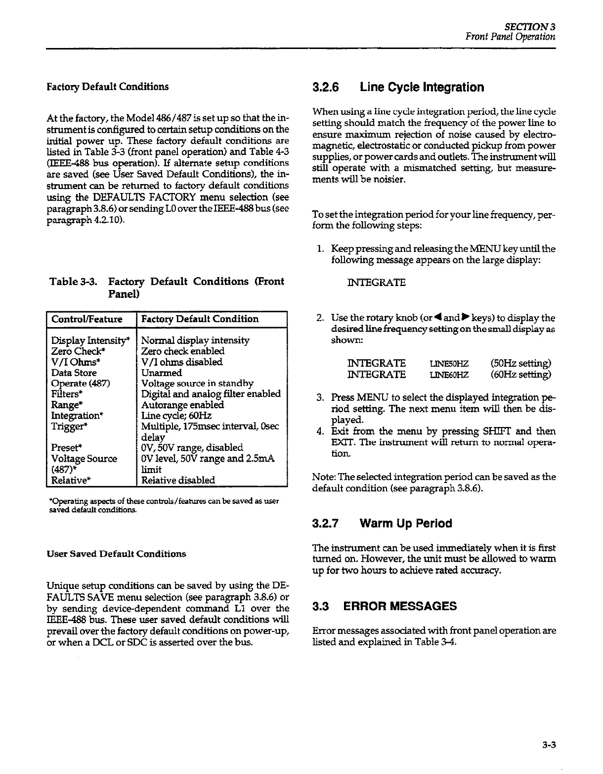
Table 3-3. Factory Default Conditions (Front
&mtmUFeatme 1 Factory Default Condition
Display Intensity” Normal display intensity
Zero Ch& Zero check enabled
V/I ohms* V/I ohms disabled
Data Store unarmed
Operate (487) Voltage source in standby
Filters* Digital and analog filter enabled
Range* Autorange enabled
Integration’ Line cycle; 6OHz
Trigger’ Multiple, 175msec interval, Osec
delay
Preset+ OV, 50V range, disabled
Voltage Source OV level, 50V range and 2.5mA
(4S7)*
limit
Relative*
Relative disabled
‘operating aspects of these conimls/feaixres can be saved a* user
saved default conditions..
User Saved Default Conditions
Unique setup conditions can be saved by using the DE-
FAULTS SAVE menu selection (see paragraph 38.6) or
by sending device-dependent comman
d
Ll over the
IEEE-488 bus. These user saved default conditions will
prevail over the factory default conditions on power-up,
or when a DCL or SDC is asserted over the bus.
3.2.6 Line Cycle Integration
When using a line cycle integration period, the line cycle
setting should match the frequency of the power line to
ensure maximum rejection of noise caused by electro-
magnetic, electrostatic or conducted pickup from power
supplies, or power cards and outlets. The instrument will
still operate with a mismatched setting, but measure
ments will be noisier.
To set the integration period for your line frequency, per-
form the following steps:
1. KeeppressingandreleasingtheMENUkeyunlilthe
following message appears on the large display:
INTEGRATE
2. Use the rotary knob (or4 and b keys) to display the
desired line frequency setting on the small display as
shown:
INTEGRATE
LlNE5OHZ
(5OHz setting)
INTEGRATE
LJNE6OHZ
WX-Iz setting)
3. Press MENU to select the displayed integration pe-
riod setting. The next menu item will then be dis-
played.
4. Exit from the menu by pressing SHIFT and than
EXE. The hstmment will return to normal opera-
tion
Note: The selected integration period can be saved as the
default condition (see paragraph 3.8.6).
3.2.7 Warm Up Period
The instrument can be used immediately when it is first
turned on. However, the unit must be allowed to warm
up for two hours to achieve rated accuracy.
3.3 ERROR MESSAGES
Error messages associated with front panel operation are
listed and explained in Table 3-4.
3-3