8. Carefully adjust R348 for a reading of 0.0030 215 count5
on the display. Iterative adjustment may be necessary.
9. Replace the top cover and secure it with the two screws
removed earlier.
REAR PANEL
._
::
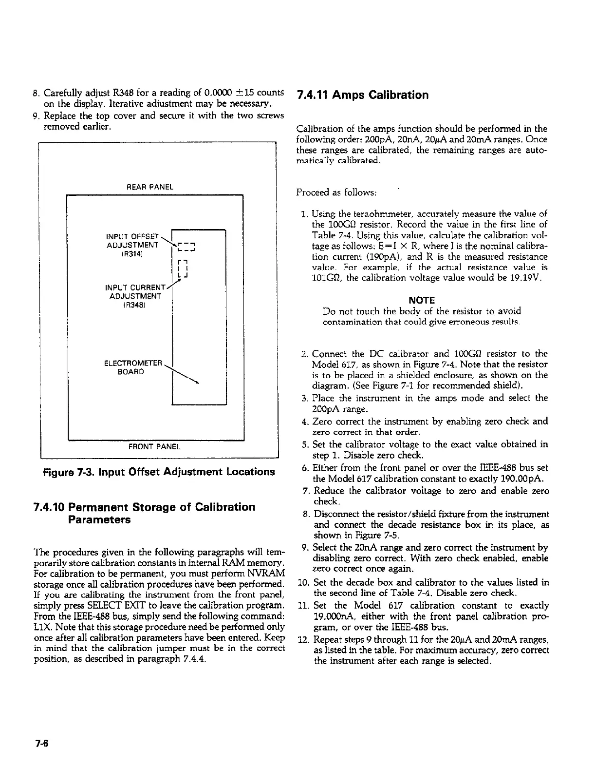
INPUT CURRENT
i’
ADJUSTMENT
,R348,
ELECTROMETER
BOARD
I
I
FRONT PANEL
Figure 7-3. Input Offset Adjustment Locations
7.4.10 Permanent Storage of Calibration
Parameters
The procedures given in the following paragraphs will tem-
porarily store calibration constants in internal RAM memory.
For calibration to be permanent, you must perform NVRAM
storage once all calibration procedures have been performed.
If you are calibrating the instrument from the front panel,
simply press SELECT EXIT to leave the calibration program.
From the IEEE-488 bus, simply send the following command:
LlX. Note that this storage procedure need be performed only
once after all calibration parameters have been entered. Keep
in mind that the calibration jumper must be in the correct
position, as described in paragraph 7.4.4.
7.4.11 Amps Calibration
Calibration of the amps function should be performed in the
following order: 2OOpA, 2OnA, 20pA and 2OmA ranges. Once
these ranges are calibrated, the remaining ranges are auto-
matically calibrated.
Proceed as follows:
’
1. Using the teraohmmeter, accurately measure the value of
the lOOGO resistor. Record the value in the first line of
Table 7-4. Using this value, calculate the calibration vol-
tage as follows: E=I X R, where I is the nominal calibra-
tion current (190pA). and R is the measured resistance
value. For example, if the actual resistance value is
lOlGR, the calibration voltage value would be 19.19V.
NOTE
Do not touch the body of the resistor to avoid
contamination that could give erroneous results.
2. Connect the DC calibrator and lOOGO resistor to the
Model 617, as shown in Figure 7-4. Note that the resistor
is to be placed in a shielded enclosure, as shown on the
diagram. (See Figure 7-l for recommended shield).
3. Place the instrument in the amps mode and select the
2OOpA range.
4. Zero correct the instrument by enabling zero check and
zero correct in that order.
5. Set the calibrator voltage to the exact value obtained in
step 1. Disable zero check.
6. Either from the front panel or over the IEEE-488 bus set
the Model 617 calibration constant to exactly 190.OOpA.
7. Reduce the calibrator voltage to zero and enable zero
check.
8. Disconnect the resistor/shield fixture from the instrument
and connect the decade resistance box in its place, as
shown in Figure 7-S.
9. Select the 2OnA range and zero correct the instrument by
disabling zero correct. With zero check enabled, enable
zero correct once again.
10. Set the decade box and calibrator to the values listed in
the second line of Table 7-4. Disable zero check.
11. Set the Model 617 calibration constant to exactly
19.ooOnA. either with the front panel calibration pro-
gram, or over the IEEE-488 bus.
12. Repeat steps 9 through 11 for the 20pA and 2OmA ranges,
as listed in the table. For maximum accuracy, zero correct
the instrument after each range is selected.
7-6