Four-wire resistance verification with offset compensation off
The values and limits in the following tables are for example only. You must calculate test limits
based on the actual resistance values output by your calibrator or resistance source (see Example
reading limit calculation (on page 2-4)).
For 10 MΩ verification, the Sense HI cable is optional. Measurement is with Input HI and LO and
Sense LO only.
Verify 2-wire resistance accuracy
To verify the 2-wire resistance function 100 MΩ range, you will:
• Use shielded, Teflon-insulated or equivalent cables in a 2-wire configuration.
• Apply accurate resistance from the calibrator to the terminals on the front panel of the DMM6500.
• Verify that the displayed readings are within specified limits.
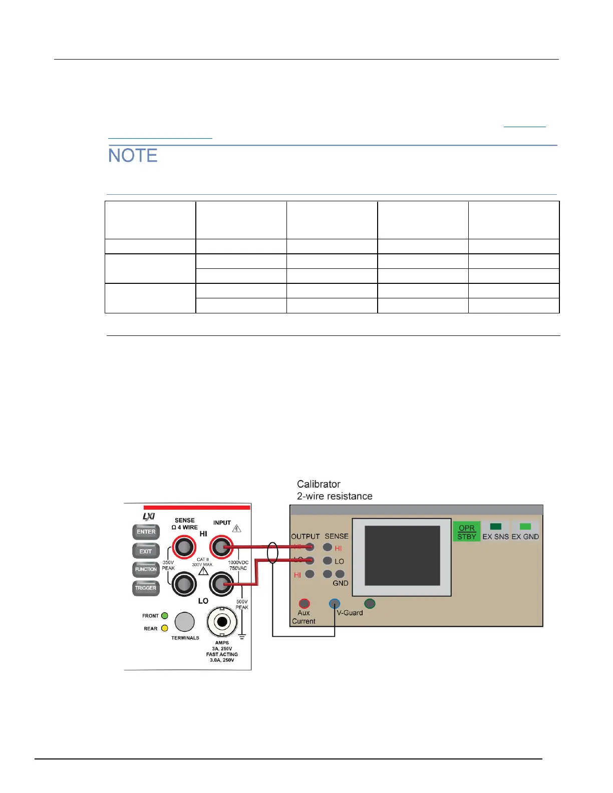
Verify resistance 100 MΩ range
To verify the 100 MΩ range:
1. Connect the DMM6500 INPUT to the calibrator as shown in the following figure.
Figure 11: Connections for 100 MΩ verification

 Loading...