2. On the DMM6500, press the FUNCTION key, select the Measure Functions tab, and select
Frequency.
3. Select the MENU key.
4. Under Measure, select Settings.
5. Set the Aperture to 250 ms.
6. Set the Threshold Range to 10 V.
7. Press the HOME key.
8. Source the voltage and frequency values as listed in Verify the frequency (on page 2-15). For
each setting, be sure that the reading is within low and high limits.
Verify the frequency
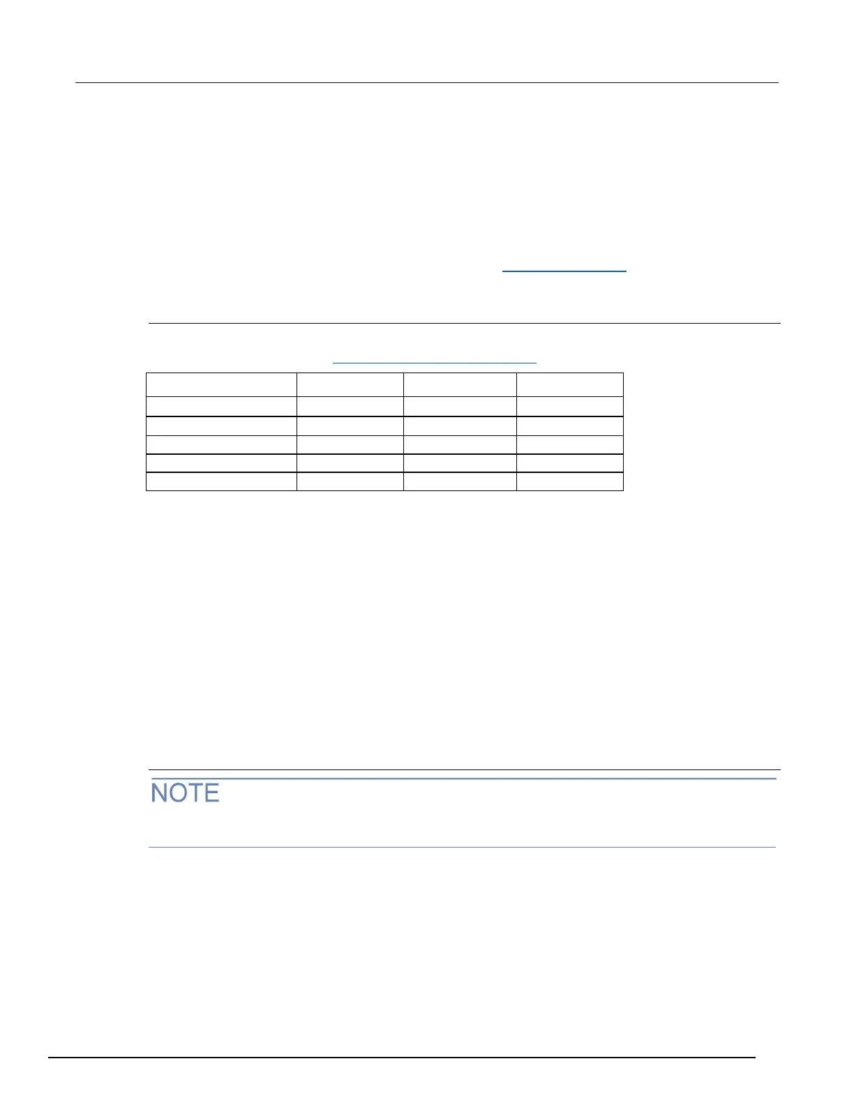
Use the following values to verify the performance of the DMM6500. Actual values depend on
published specifications (see Example reading limit calculation (on page 2-4)).
Simulated thermocouple Type J temperature verification
To verify thermocouple accuracy, you will:
• Apply accurate voltages from the calibrator to the terminals on the front panel of the DMM6500.
• Verify that the displayed readings are within specified limits.
Thermocouple accuracy is verified by using a DC voltage calibrator to output values from standard
thermocouple tables available from the National Institute of Standards and Technology (NIST) or
other sources.
In the table following the steps below, three representative values are listed from a Type J
thermocouple table for temperatures –190 °C, 0 °C, and 750 °C, with their respective thermocouple
voltages listed in the “Uncompensated calibrator source value” column. The calibrator source values
are based on NIST Monograph 175, reference data 60, version 2.0.
Verify thermocouple accuracy
Because the cable connecting the calibrator to the DMM6500 can have non-trivial thermal offset
voltages, you must first correct for these to verify the DMM6500 specifications.
To verify the simulated thermocouple Type J temperature:
1. Connect the DMM6500 HI and LO INPUT terminals to the calibrator HI and LO terminals as
shown in the following figure.

 Loading...