19. Set the calibrator to the simulated thermocouple voltage you want (from the following table), first
correcting for the offset voltage measured in step 14. For example, if the measured offset voltage
was –2 µV, set the calibrator to –7.659 mV – (–0.002 mV), which equals –7.657 mV, to simulate –
190 °C.
20. Verify that the DMM6500 reading is within lower and upper limits.
21. Repeat steps 17 and 18 for each value in the following table.
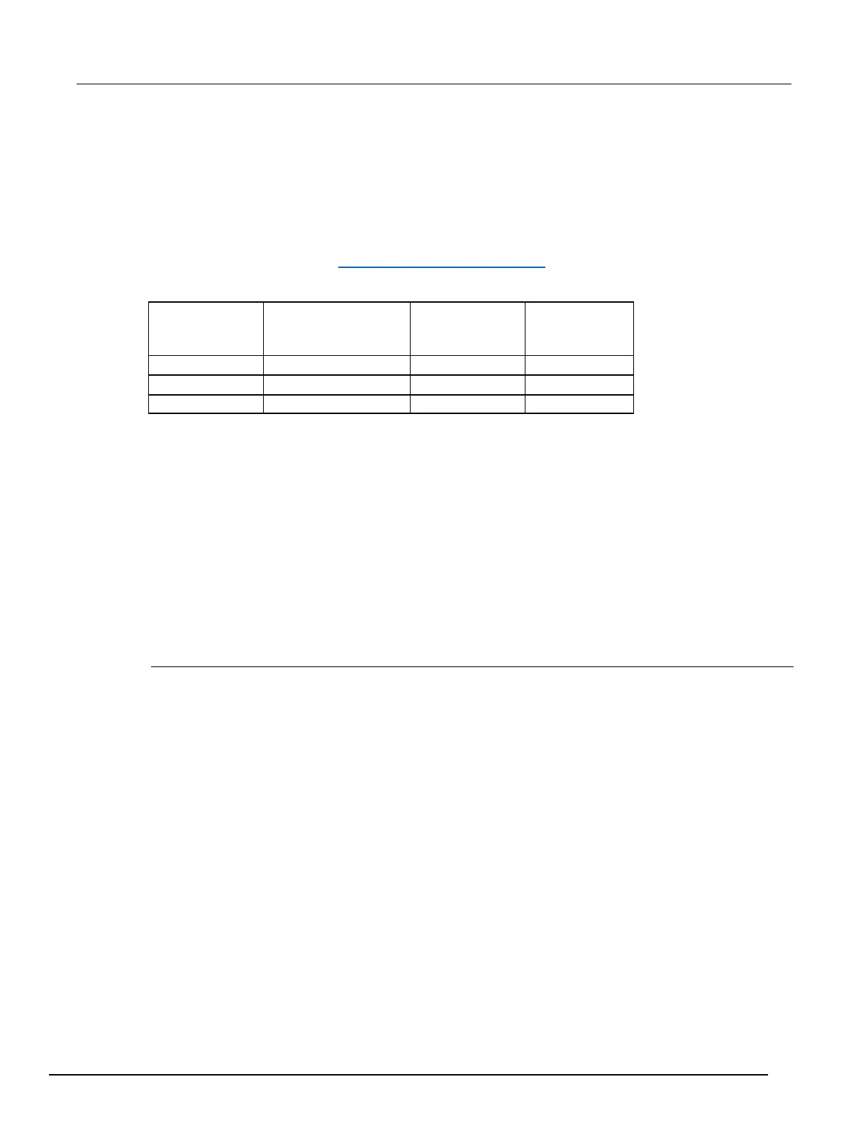
Use the following values to verify the performance of the DMM6500. Actual values depend on
published specifications (see Example reading limit calculation (on page 2-4)).
Simulated RTD temperature verification
Use the following information to verify the performance of the DMM6500. Actual calibrator source
values will vary. RTD verification is based on the calibrator sourcing resistance and the DMM6500
conversion of the resistance measurement to calculated temperature based on the Callendar-Van
Dusen equation.
To verify RTD temperature accuracy, you will:
• Apply accurate resistance from the calibrator to the terminals on the front panel of the DMM6500.
• Verify that the displayed readings are within specified limits.
RTD equations
The temperature versus resistance readings listed in the RTD reference tables are calculated using
the Callendar-Van Dusen equation. There are two equations that are based on different temperature
ranges. There is an equation for the –200 °C to 0 °C range and one for the 0 °C to 850 °C range.
Equation for –200 °C to 0 °C temperature range
RRTD = R0 [1 + AT + BT2 + CT3(T – 100)]
where:
• R
RTD
is the calculated resistance of the RTD
• R
0
is the known RTD resistance at 0 °C
• T is the temperature in °C
• A = alpha [1 + (delta/100)]
• B = –1 (alpha)(delta)(1E-4)
• C = –1 (alpha)(beta)(1E-8)
The alpha, beta, and delta values are listed in the following table.

 Loading...