Flexlite GX
Operating manual - EN
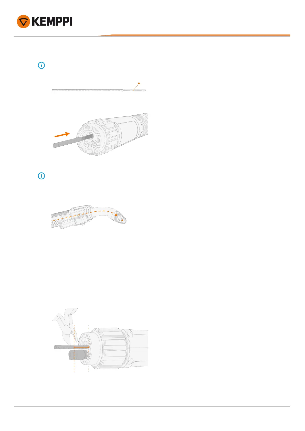
4. Feed the new wire liner into the cable hose until it stops at the gun neck end.
The standard steel wire liner includes a stripped steel spiral section(*) at its front end. This section goes in first. The
steel wire liner for a multi-neck welding gun does not include a stripped section.
To ensure that the wire liner is in the correct position, temporarily remove the welding gun contact tip. For more
information on the contact tip, refer to "About equipment" on page5 and "Assembling gun" on page8. In case of a
multi-neck welding gun, the wire liner does not go into the neck. With a multi-neck welding gun, the neck is to be
removed (refer to "Replacing wire liner for multi-neck" on page21).
For finalizing the wire liner installation, refer to (depending on your welding gun model):
"Installing sleeve assembly and cutting wire liner (Euro connector:series 3 and 5 welding guns)" below or
"Installing sleeve assembly and cutting wire liner (Kemppi connector: series 8 welding guns)" on the next page.
Installing sleeve assembly and cutting wire liner (Euro connector:series 3 and 5 welding guns)
The method is the same for both gas- and water-cooled welding guns.
1. Insert the sleeve nut next to the wire liner for measure.
2. Using side cutting pliers, cut the wire liner flush with groove in the sleeve nut end.
© Kemppi
18
1921390 / 2310
 Loading...