2 Operating Your Frequency Counter
100 Keysight 53150A/151A/152A Operating Guide
10 To add or adjust the values in another data point, press the left-arrow key
repeatedly until “PWR CORR” is re-displayed, and repeat steps 2 through 10.
To edit data points within another power-correction profile, press the
left-arrow key repeatedly until “PWR CORR” is re-displayed, and repeat steps
1 through 10.
11 If you are done entering data-point values, press the Enter key to accept your
changes, save the data-point values, and return to the measurement display.
Power Correction is now enabled using the profile number 3.
NOTE
When a data point is entered in a profile, all of the data points in that profile are
sorted by frequency and stored in that order. Therefore, the data points in a
profile are always in order from the lowest frequency to the highest when you
access a correction profile. The first data point displayed is always the data point
that contains the lowest frequency value.
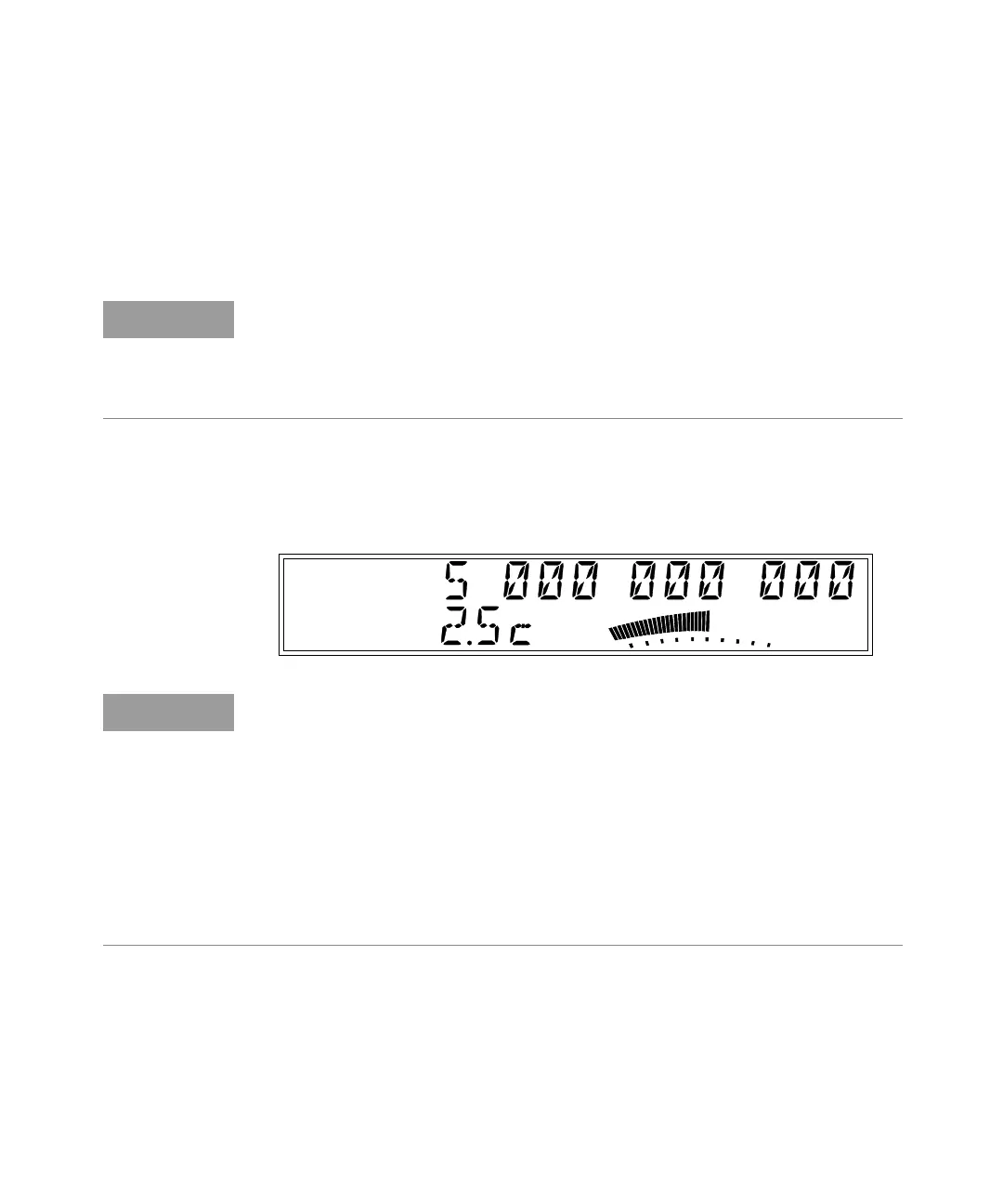
Ch 2
Freq
Pwr
dBm
NOTE
You can include your selection of a power-correction profile in any of the nine
sets of user settings stored in non-volatile memory (see page 109) by enabling
the profile and then saving the set. If you save set 0 (zero) while
Power-Correction is enabled, the currently-selected profile will be in effect
whenever you turn on the Counter.
The data in the saved user settings and in all of the power-correction profiles is
stored in non-volatile memory. If the Counter ever requires repair, and the main
circuit-board assembly is replaced, these stored values will be lost. Therefore, to
protect these values and ensure they are available for future use, you should
keep an external record of them.