Front-panel instructions
In these procedures, the term "UUT" means "unit under test," or the AC6801B, AC6802B,
AC6803B, or AC6804B.
The tables below provide the test procedures for verifying the AC6801B, AC6802B, AC6803B, and the
AC6804B, in compliance with the instrument's specifications. Please refer to the calibration procedure
if you observe out-of specification performance. The performance test specifications are listed in the
Performance Test Records at the end of this chapter. You can record the actual measured values in
the columns provided. When performing the load tests select an adequate gauge wire using the
procedures given in the User’s Guide for connecting the load.
Voltage Programming and Readback Accuracy
This procedure verifies that the voltage programming and readback functions are within specifications.
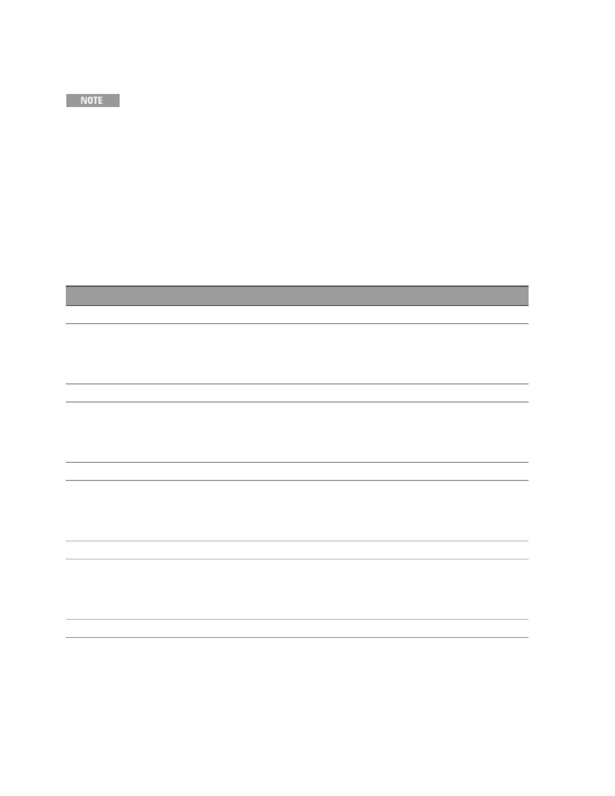
Step Action Normal Result
1 Turn off the UUT and connect the DMM across the output as shown above.
2 Turn on the UUT. Program output to:
RANGE 155 V, VOLT 155, FREQ 60
Voltage at 155 Vrms
CV annunciator on
Output current near zero
3 Record voltage readings at DMM and on front panel display. Reading within specified low range limits
4 Turn on the UUT. Program output to:
RANGE 310 V, VOLT 310, FREQ 60
Voltage at 310 Vrms
CV annunciator on
Output current near zero
5 Record voltage readings at DMM and on front panel display. Reading within specified high range limits
6 Program RANGE155 V, VOLT 155, FREQ 500 Voltage at 155 Vrms
CV annunciator on
Output current near zero
7 Record voltage readings at DMM and on front panel display. Reading within specified low range limits
8 Program RANGE 310 V, VOLT 310, FREQ 500 Voltage at 310 Vrms
CV annunciator on
Output current near zero
9 Record voltage readings at DMM and on front panel display. Reading within specified high range limits
Keysight AC6800B Series Operating and Service Guide 179
4Calibration, Verification, and Service