Keysight B1500A User’s Guide, Ed ition 14 3- 27
Installation
Installing Accessories
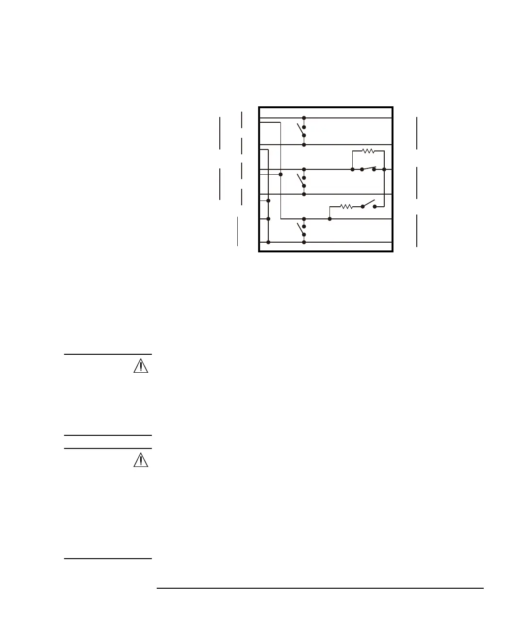
Figure 3-9 N1255A Internal Connections
• SW1: Kelvin/Non-Kelvin selection switch for High1
• SW2: Kelvin/Non-Kelvin selection switch for High2
• SW3: Kelvin/Non-Kelvin selection switch for Low
•SW4: 0 /100 series resistor selection switch for High2 Force
•SW5: Open/50 shunt resistor selection switch between High2 and Low, Force
NOTE
Selection switch SW2 and SW4
The SW4 switches the series resistance 0 /100 on the High2 Force line. The
resistor is not mounted on the High2 Sense line.
Set the SW4 to “0 ” if the SW2 is set to “Kelvin”.
Set the SW2 to “Non-Kelvin” if the SW4 is set to “100 ”.
NOTE
Selection switch SW1/SW2/SW3 and Sense connector on Output panel
The switch is used to make or break the connection between Force and Sense in the
N1255A. Setting it to “Non-Kelvin” makes this internal connection to enable the
non-Kelvin connection. And setting it to “Kelvin” breaks this internal connection to
enable the Kelvin connection.
If the switch is set to “Non-Kelvin”, do not extend the Sense output corresponding
to it. Voltage on the Force line also appears on the Sense line. So, open the Sense
connector on the Output panel.
Sense
N1255A Connection Box
Force
Force
Sense
Force
Force
Sense
Sense
Force
Sense
High1
Force
Sense
High2
MCSMU1
MCSMU2
GNDU/SMU
Low
Low
High
Low
High
Low
High
Low
High
50 Ω
100 Ω
SW4
SW5
SW3
SW2
SW1