3- 60 Keysight B1500A User’s Guide, Edition 14
Installation
About Plug-in Modules
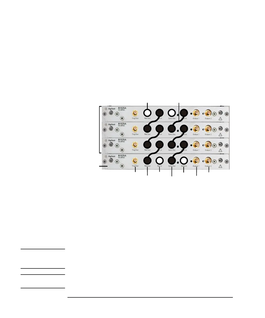
To Interconnect SPGUs
If multiple SPGUs have been installed, connect the SPGUs by using the following
parts furnished with the SPGU. See Figure 3-24.
• SPGU Sync cable, 16493Q-001, (number of SPGUs -1)2 ea.
• RF connector cap, 1253-7431, 4 ea.
Figure 3-24 SPGU Module Connection Example, Four Modules
If multiple SPGUs have been installed, connect the SPGUs as shown in Figure 3-24.
This connection makes it possible to perform the synchronous output by the
multiple SPGU channels. In this figure, the master SPGU is the module which
outputs the reference signal and the slave SPGUs are the modules which follow to
the reference signal.
Connect the RF connector cap to the Ref In and Sync In connectors on the master
SPGU and the Ref Out and Sync Out connectors on the last slave SPGU.
The Trig Out terminal must be connected to the trigger input terminal of the external
equipment to make the synchronized operation of it.
CAUTION Connect the Ref Out/In, Sync Out/In, and Trig Out terminals to the specified
terminal properly. Connecting to the other terminal may result in damage to the
SPGU.
NOTE The B1500A does not support the synchronized operation between SPGU and
WGFMU.
Master SPGU
Slave SPGU
Trig Out
Ref Out
Ref In
Sync Out
Sync In
Output 1
Output 2
SPGU Sync cable
RF connector cap