Keysight B1500A User’s Guide, Ed ition 14 3- 41
Installation
Mounting Connectors
To Connect MCSMU Output
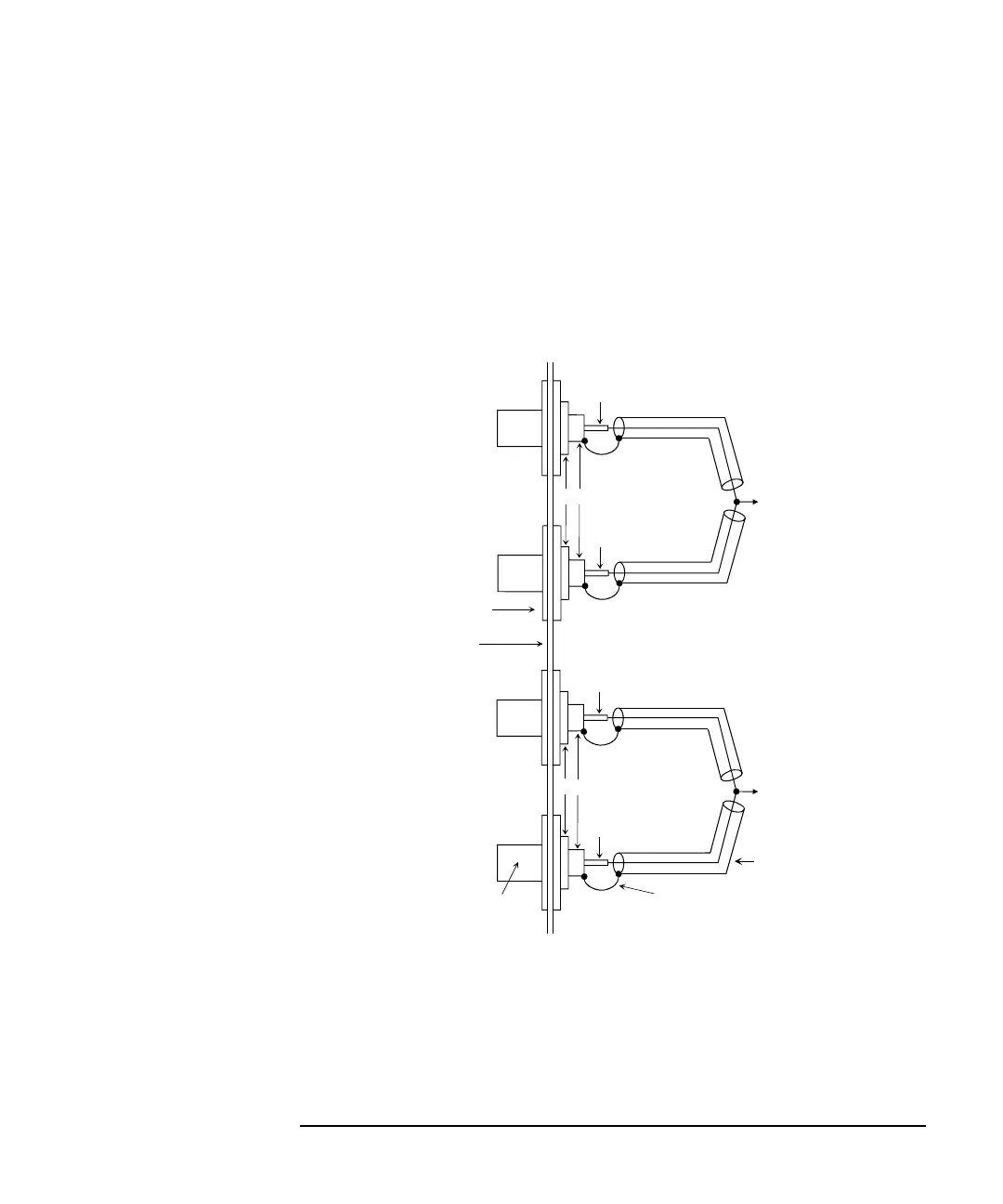
The MCSMU output connection example is shown in Figure 3-20.
For the connection of the MCSMU, the N1255A connection box is required. See
“To Connect MCSMU Connection Box” on page 3-26 to connect the MCSMU to
the N1255A Input terminals. To connect the N1255A Output terminals to the
connectors as shown in Figure 3-20, use the 16494A triaxial cable.
Figure 3-20 MCSMU Output Connection
The High Force/High Sense/Low Force/Low Sense lines should be connected to the
DUT as shown above. Wiring shown in “To Connect SMU Output” on page 3-35
can be used. To simplify the connections, omit the wiring of the Common.
For the non-Kelvin connection, use the High Force and the Low Force only. Omit
the wiring of the High Sense and the Low Sense.
Common
Common
Insulator
Plate
Coaxial cable
From N1255A Output
High Force
High Sense
Low Force
Low Sense
To DUT
High terminal
To DUT
Low terminal
Triaxial connector
Wire
High Force
High Sense
Low Force
Low Sense
From N1255A Output