Keysight B1500A User’s Guide, Ed ition 14 3- 31
Installation
Mounting Connectors
To Make an Interlock Circuit
The interlock circuit is designed to prevent electrical shock when a user touches the
measurement terminals.
CAUTION You must install an interlock circuit on a shielding box to prevent hazardous
voltages when the door of the shielding box is open.
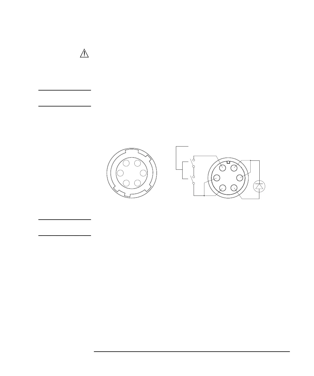
Figure 3-11 shows the pin assignments of the interlock connector that should be
mounted on a connector plate or test fixture.
Figure 3-11 Interlock Connector Pin Assignments
WARNING Potentially hazardous voltages may be present at the Force, Guard, and Sense
terminals when the interlock terminals are shorted.
Interlock switch
Wiring side
LED
1
2
3
4
5
6