3- 32 Keysight B1500A User’s Guide, Edition 14
Installation
Mounting Connectors
Installing the interlock circuit
Install the interlock circuit as follows:
1. Mount two mechanical switches on your shielding box, so that the switches
close when the door of the shielding box is closed, and open when the door is
opened. For the dimensions of the switch, see Figure 3-13 and Figure 3-14
below.
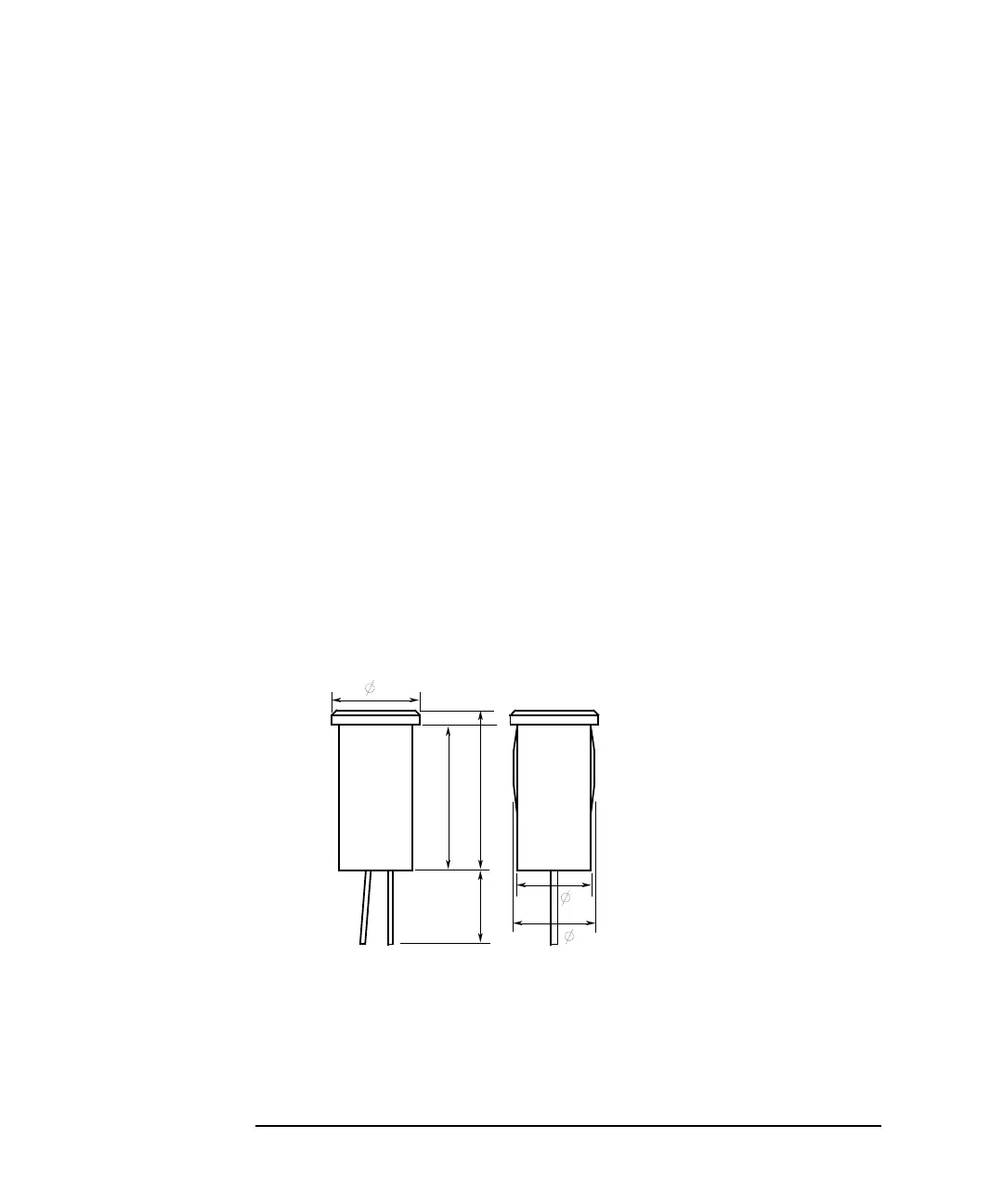
2. Mount an LED on your shielding box. For the dimensions of the LED, see
Figure 3-12.
3. Use wire to connect the two switches in series between pin number 1 and 2 (or
3) of the interlock connector. See Figure 3-11.
4. Use wire to connect the LED between pin number 4 and 5 (or 6) of the interlock
connector. See Figure 3-11.
If Keysight B1500A Interlock connector is connected to the interlock circuit,
Keysight B1500A SMU cannot force more than ± 42 V when the door is open.
When the door is closed, it can force more than ± 42 V.
When more than ± 42 V is forced from an SMU, the LED lights to indicate high
voltage output.
Figure 3-12 Dimensions of the LED (1450-0641)
6
10
11
5
5.6
5
Units: mm
Anode (+)
Cathode (-)