Keysight B1500A User’s Guide, Ed ition 14 2- 35
Introduction
Measurement Modules
HVSPGU - High Voltage SPGU
This section describes key specification of the high voltage semiconductor pulse
generator unit (SPGU). Maximum five modules can be installed in one mainframe.
• Number of output channels: 2 channels per module
• Output impedance: 50
• Output level: 0 to ± 40 V (open load), ± 20 V (50 load), 1 mV resolution
• SPGU operation mode:
PG (pulse generator) or ALWG (arbitrary linear waveform generator)
• Channel output operation mode:
Free run, duration, or pulse count (PG mode)/sequence count (ALWG mode)
• PG output mode:
2-level pulse or 3-level pulse, for each channel
• Pulse timing parameters: (programmable range)
Period: 20 ns to 10 s, 10 ns resolution
Width: 10 ns to period-10 ns, resolution 2.5 ns or 10 ns (transition time > 8 s)
Delay: 0 to period-20 ns, resolution 2.5 ns or 10 ns (transition time > 8 s)
Transition time (leading time or trailing time): 8 ns to 400 ms, resolution 2 ns or
8 ns (transition time > 8 ms)
• Pulse switch, which is more durable than mechanical relays, and better suited for
frequent switching applications.
• Automatic voltage level adjustment by specifying load impedance of DUT
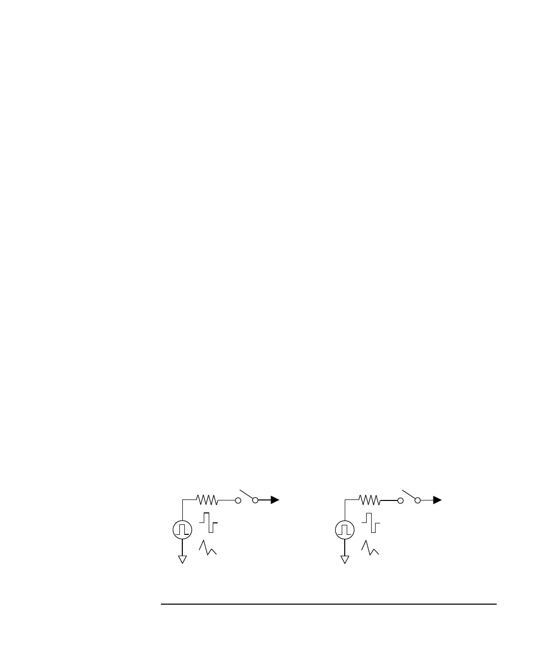
Figure 2-8 SPGU Simplified Circuit Diagram
50
7
Pulse switch
ALWG
PG
2-level
or 3-level
Output 2
or
50
7
Pulse switch
ALWG
PG
2-level
or 3-level
Output 1
or