Keysight B1500A User’s Guide, Ed ition 14 3- 37
Installation
Mounting Connectors
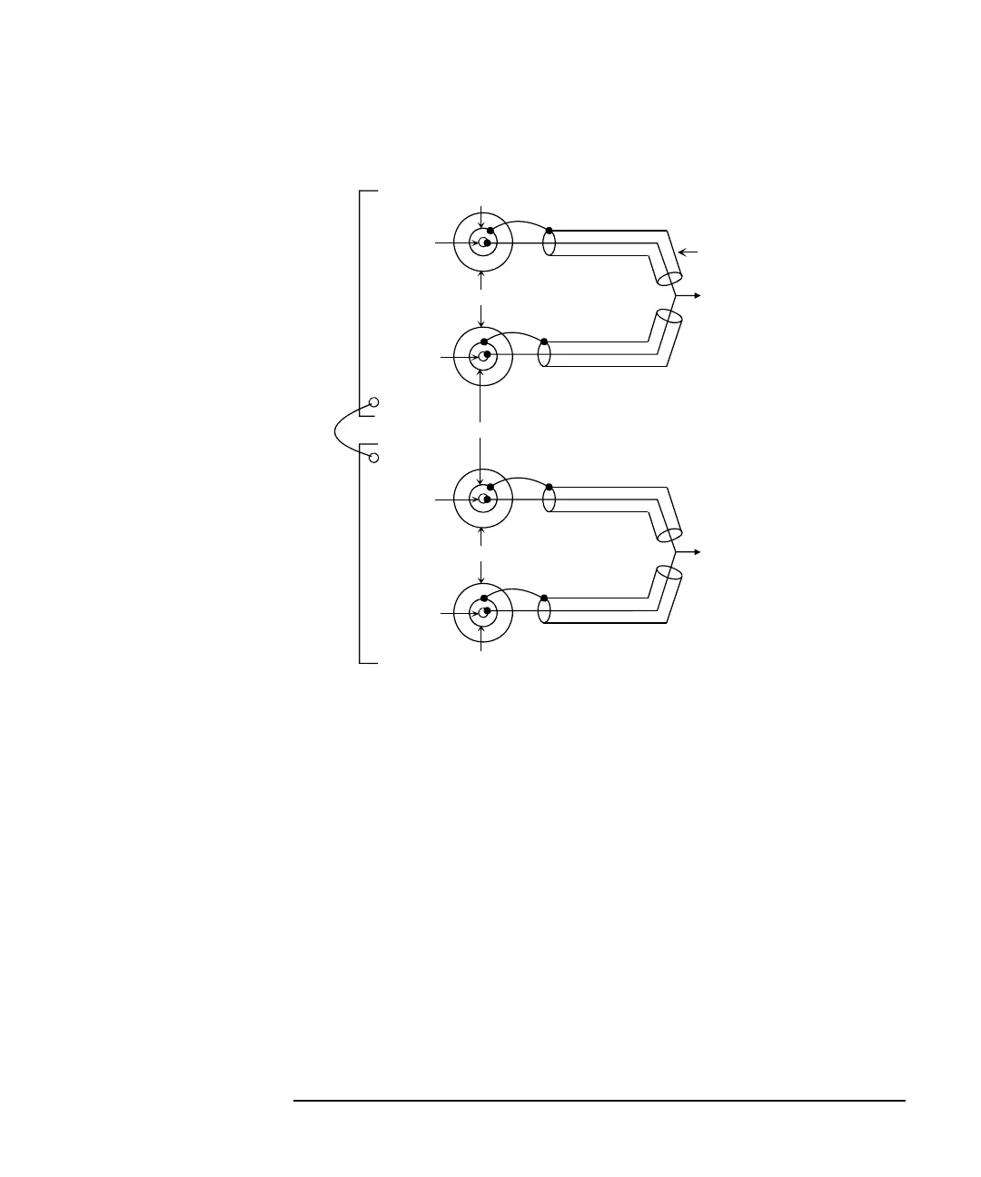
Figure 3-16 ASU Output Kelvin Connection (Remote Sensing)
The ASU inputs can be connected to the instruments by using a control cable, a
triaxial cable, and two coaxial cables. The cables can be connected to the ASU
inside the shielding box through the 16495K plate.
The ASU outputs should be connected to the DUT by using coaxial cables and wires
as shown above.
When a SMU is used for the measurements, the Kelvin paths will work as same as
Table 3-8.
When a four-terminal pair (4TP) instrument is used, the sense lines can be ignored.
And a Kelvin path is used for the high signal, and the other one is used for the low
signal. For the accurate impedance measurements, a wire must be connected
between the ASU#1 CMU Return and the ASU#2 CMU Return.
If the 4TP instrument is not used, you can ignore the CMH, CML, CMU Return, and
the DUT1 high and low terminals.
to DUT 1 or
DUT 1 high terminal
Coaxial cable
to DUT 2 or
DUT 1 low terminal
Guard
Common
Guard
CMH
or Force
Sense
Wire
Guard
Common
CML
or Force
Sense
ASU
#1
ASU
#2
CMU Return
CMU Return