106
This section provides supplemental information for the measurements by using
N1259A Option 300 Module Selector. The configuration is for 20 A solution.
B1505A 20 A configuration uses following modules.
Agilent B1505A Power Device Analyzer/Curve Tracer (20 A):
●
1 X HVSMU (B1513A) High Voltage SMU
●
1 X HCSMU (B1512A) High Current SMU
●
2 X HPSMU (B1510A) High Power SMU (Note: only one HPSMU is used in the
example)
●
1 X MFCMU (B1520A) Multi-Frequency CMU
Following shows the N1259A test fixture configuration and cables used for connect-
ing between B1505A and the N1259A.
Agilent N1259A High Power Test Fixture:
●
Opt 020 High Voltage Bias Tee
●
Opt 300 Module Selector (Optional: Check appendix section for using the Module
Selector)
●
Opt 010 Inline package socket module (3 pin)
●
Opt 022 100 kΩ R-Box (Optional)
●
Opt 033 1 kΩ R-Box
●
(10 X Test leads, 2 X SHV cables and SHV-Banana adapters are including in the
N1259A)
Appendix 2. Preparation for the Measurements using the Module Selector
A2-1. Instruments and Accessories used in the measurement examples
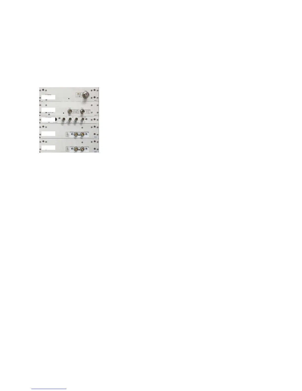
HCSMU
HPSMU
MFCMU
HVSMU
HPSMU
Figure A2-1. B1505A 20 A configuration used in the example.

 Loading...


