108
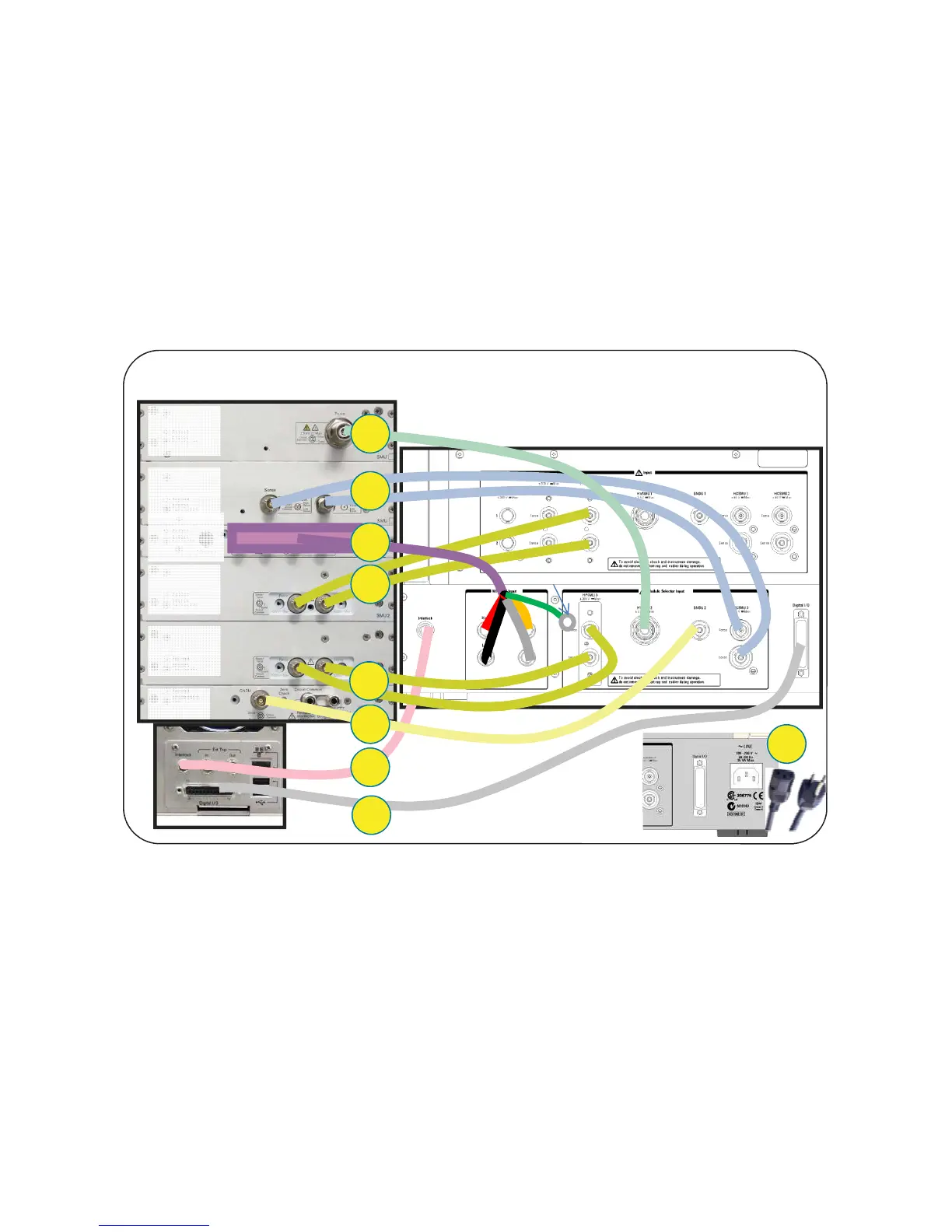
Before starting the measurements, connect the cables between the B1505A and the
N1259A as shown in figure A2-3.
The breakdown of each step with cable figures and the connector locations are
shown in figure A2-4.
These connections are used for all the measurement examples, and there is no need
for changing this configuration.
Step number1:
Using a 16493G Digital I/O Cable, connect the Digital I/O connector on the
B1505A to the Digital I/O connector on the N1259A test fixture.
Step number 2:
Using a 16493J Interlock Cable, connect the Interlock on the B1505A and the
Interlock on the N1259A
Tips:
For connecting the interlock cable, hold the black plastic part and then turn
the connector by pressing toward the interlock connector in the instrument
A2-2. Cable Connection between the B1505A and the N1259A Test Fixture
Figure A2-3. Total connection setup for the measurement with the Module Selector.
Back side of the B1505A
Back side of the N1259A
2
4
3
5
6
7
8
Connections for 1x HCSMU Configuration (20 A) with Opt 300 Module selector
Leave it open
B1513A
HVSMU
B1512A
HCSMU
B1510A
HPSMU
B1510A
HPSMU
B1520A
MFCMU
GNDU
CoaxTriax
Coax
Triax
1
9

 Loading...


