Installation 2
Series E4360 User’s Guide 35
Auto-Parallel Connections
NOTE
For the firmware to correctly control the paralleled output channels,
you must specify that the output channels are connected in auto-
parallel, and which channel is configured as the master and which
channels are configured as followers. Refer to chapter 4 under
“Configuring Paralleled Outputs”.
Auto-Parallel in Fixed mode
Auto-parallel connections are used to ensure equal current sharing
when the outputs of up to four mainframes are paralleled. In this
configuration, a “master” channel provides an analog current
programming signal on its “IM-” analog output pin, which programs the
output current of all “follower” channels that are connected to it.
However, this method requires additional analog connections to be
made between the output channels and the mainframes.
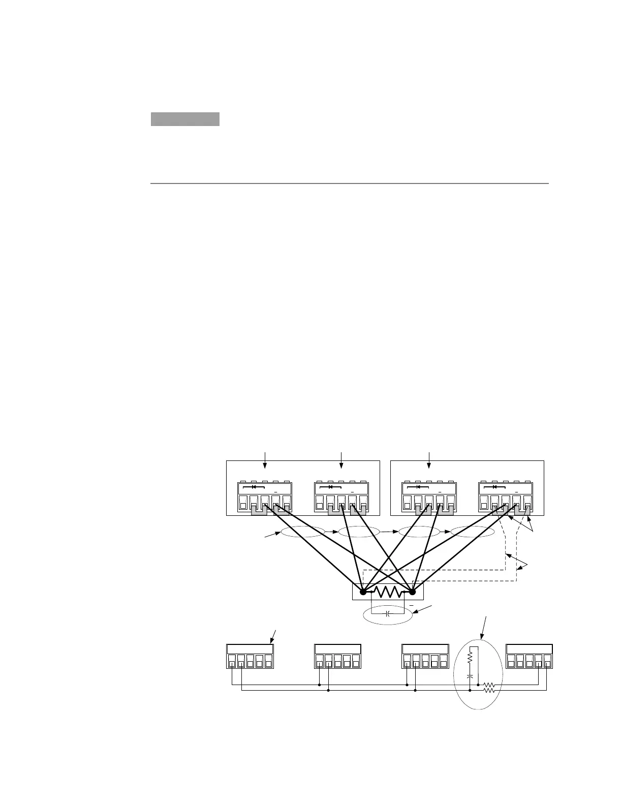
The following figure illustrates Fixed mode connections. If remote
sensing is required, connect the remote sense terminals of all outputs to
the load as shown by the dashed lines in the figure. To avoid output
ringing, you can either connect an output capacitor across the load as
shown in (5a), or you can connect a filter across the current monitoring
connections as shown in (5b). This network consists of two 200 ohm
resistors in series with the current monitor lines going to the master
output, and an RC paralleled across the current monitor lines. Chose
only one method (5a or 5b).
1 Master output
2 Follower outputs
3 Twist or bundle wire
pair
4 Analog connectors
(one for each output)
5 Optional components
to reduce output
ringing. Select only
ONE of the two
methods shown:
(5a or 5b).
6 Sense jumpers
installed.
For remote sensing,
remove the sense
jumpers and connect
sense wires (7)
for ALL outputs.
(Only one output is
illustrated to simplify
the figure.)
IP+
IP- SAS P IM-
ANALOG
output 2
IP+ IP- SAS P IM-
ANALOG
output 1
IP+ IP- SAS P IM-
ANALOG
output 2
IP+ IP- SAS P IM-
200
200
68
0.15
4
5b
+D +s + -s
+D +s + -s
+D +s + -s
+D +s + -s
E4360A
output 1
1
Master
2
output 2
E4360A
output 1
22
output 2
ANALOG Master
output 1
9
.9
+
5
a
7
6
R
Load
3