2 Installation
36 Series E4360 User’s Guide
As shown in the following table, the capacitor values required for the two
compensation methods depend on the number of follower outputs that
are paralleled.
# of Follower outputs
Output capacitor (5a)
RC values (5b)
1
2
3
3.3 µF min. (< 6Ω ESR)
6.6 µF min. (< 3Ω ESR)
9.9 µF min. (< 2Ω ESR)
0.47 µF/68 Ω
0.1 µF/68 Ω
0.15 µF/68 Ω
When programming the output current, program only the master output
channel with 1/nth of the desired current, where n is the number of
output channels paralleled. The follower outputs will generate the same
current as the master. Set the current protection of the follower outputs
to the same value as the master output. Set the output voltage of the
follower outputs slightly higher than the output voltage of the master
output. Output status, voltage readback, and current readback must be
returned individually for each output.
If the outputs are grouped in auto-parallel mode as explained in
Appendix D, the master output channel must be channel 1 in one of the
frames. All other output channels must be connected as followers.
Auto-Parallel in SAS and Table modes
NOTE
Auto-parallel operation is available in SAS and Table modes; however,
better current programming accuracy is obtained for individual outputs
in direct-parallel operation.
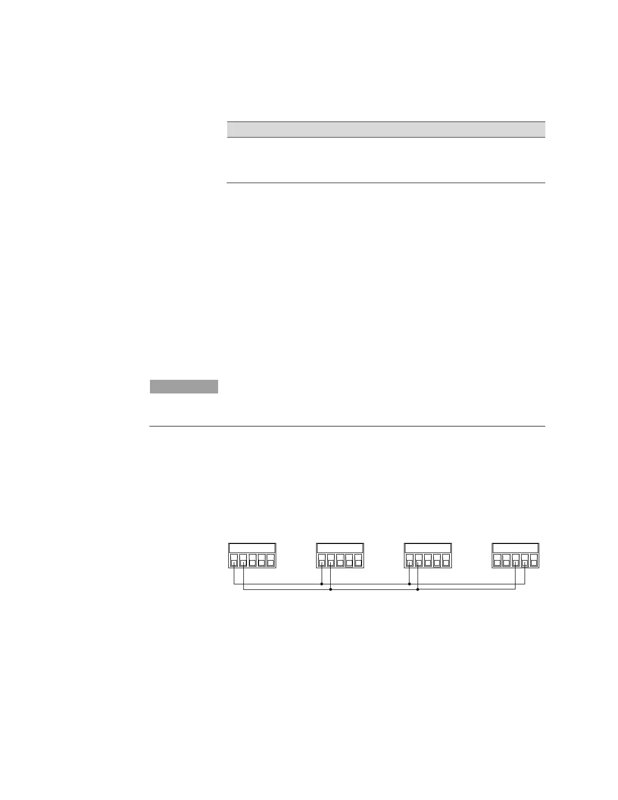
Auto-parallel operation is in SAS and Table mode is similar to Fixed
mode except that the compensation circuits shown in 5a and 5b in the
previous figure are not required. Also, the SAS pin is connected on the
Analog master port as shown below. Note however, because the analog
control signal from the “master” is not calibrated, better current
programming accuracy is obtained when output are connected in direct
parallel.
As in Fixed mode, you must specify which output channel is the master
and which outputs are followers. Refer to chapter 4 under “Configuring
Paralleled Outputs”. In SAS mode, the same model parameters or list
step must be in effect for each output channel. If lists are used, each
output must get the same list steps and triggering to cause the outputs
to change steps at the same time. In Table mode, the same user-table
must be activated for all outputs.
IP+ IP- SAS P IM-
ANALOG
output 2
IP+ IP- SAS P IM-
ANALOG
output 1
IP+ IP- SAS P IM-
ANALOG
output 2
IP+ IP- SAS P IM-
ANALOG Master
output 1