Getting Started 1
Keysight InfiniiVision 1000 X-Series Oscilloscopes User's Guide 29
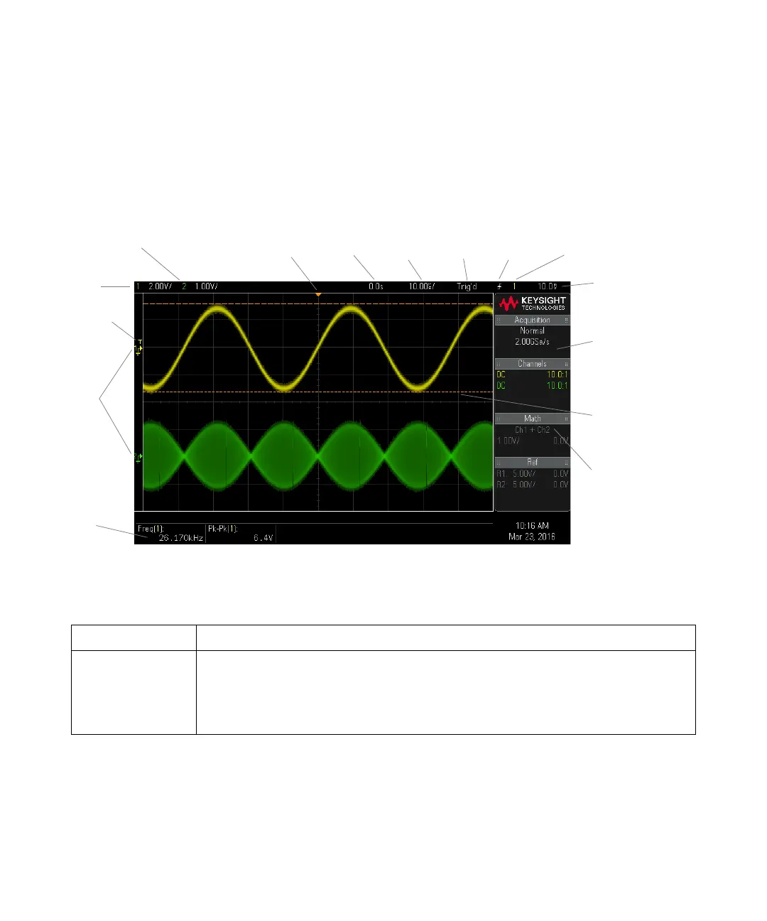
Learn the Oscilloscope Display
The oscilloscope display contains acquired waveforms, setup information,
measurement results, and the softkey definitions.
Figure 1 Interpreting the oscilloscope display
Analog channel
sensitivity
Status line
Analog
channels
and ground
levels
Trigger level
Trigger point,
time reference
Delay
time
Time/
div
Run/Stop
status
Trigger
type
Trigger
source
Measurements
Trigger level
Softkey labels
and information
area
Cursors defining
measurement
Other
waveforms
Status line The top line of the display contains vertical, horizontal, and trigger setup information.
Display area The display area contains the waveform acquisitions, channel identifiers, and analog trigger, and
ground level indicators. Each analog channel's information appears in a different color.
Signal detail is displayed using 256 levels of intensity.
For more information about display modes see "Display Settings" on page 49.

 Loading...


