162 Keysight CXG, EXG, and MXG X-Series Signal Generators Service Guide
Front Panel Assembly
Troubleshooting
RPG Failures
If there is an RPG failure and the front panel key test passes the problem is
most likely either the A6A4 Keyboard, the A6A1 Front Panel Interface board, or
the ribbon cable W3 that connects them together. To isolate the problem, use
the following procedure:
1. Remove the front panel from the instrument while leaving W1 connected
to both the instrument and the front panel assembly. See Chapter 15,
“Assembly Replacement,” for instructions on how to remove and replace
the A6 Front Panel assembly.
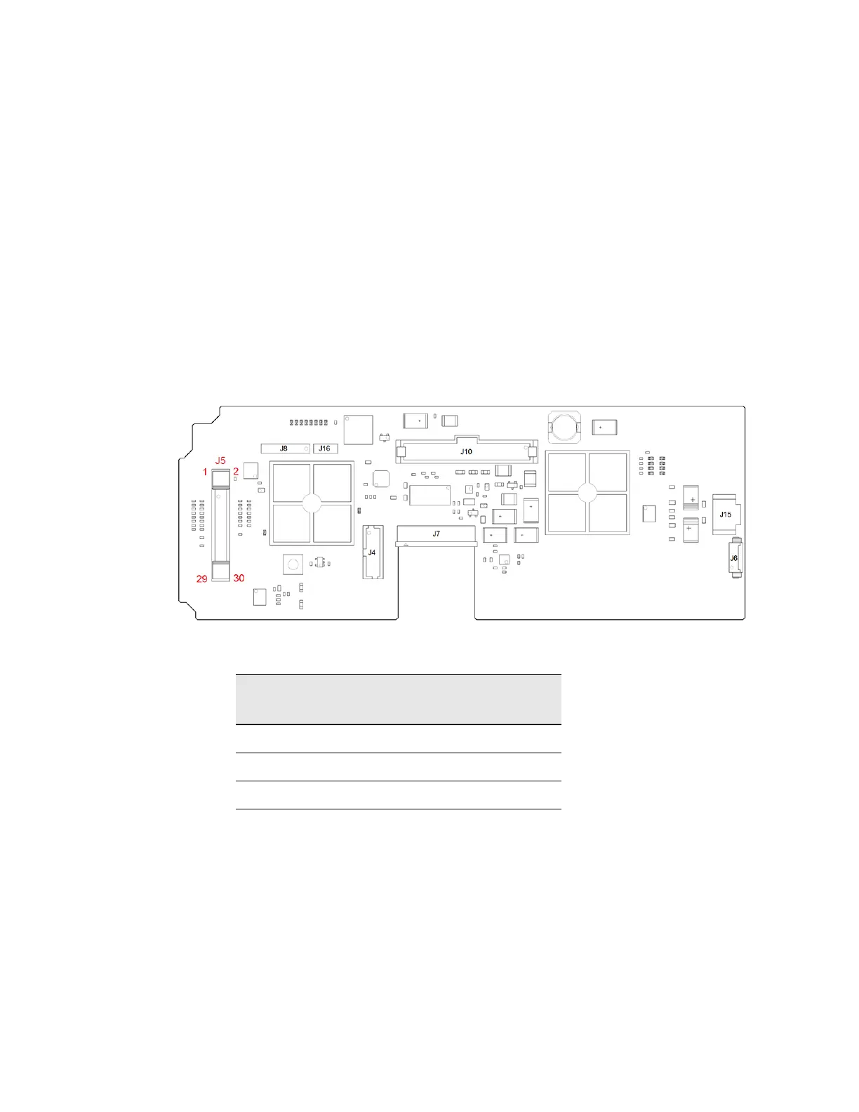
2. Referring to Figure 7-2, probe each of the RPG control lines on A6A1 J5
listed in Table 7-1 with an oscilloscope and verify that the levels indicated
are present.
Figure 7-2 A6A1 J5 Pinout
3. If there is no +5 VDC at pin #28, replace the A6A1 Front Panel Interface
board.
If there is +5 VDC at pin #28 but either pin # 26 or 30 has no pulses when
the RPG is rotated, replace the A6A4 Keyboard.
If all the levels are correct, replace the A6A1 Front Panel Interface board.
Table 7-1 RPG Control line Expected Levels
A6A1 J5 Pin # RPG State Expected Level
(+/-10%)
26 Rotating +4 V Pulses
28 Steady +5 VDC
30 Rotating +4 V Pulses
 Loading...


