222 Keysight CXG, EXG, and MXG X-Series Signal Generators Service Guide
RF Assembly
A3 RF Assembly Troubleshooting
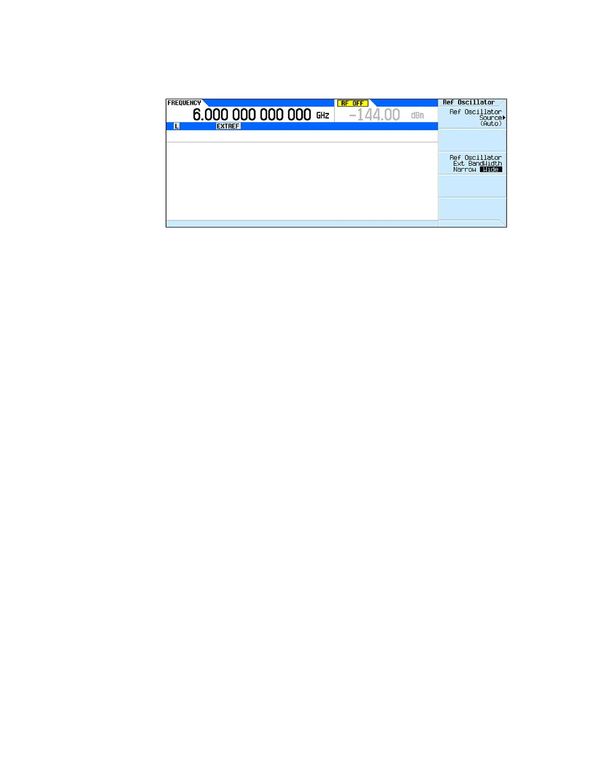
Figure 10-12 External Reference Indicator
8. Reduce the power level of the additional source to -3 dBm and verify that
the EXTREF indicator is still on and that there is no reference unlock error
on the display.
Increase the power level of the additional source to +20 dBm (or as high as
it will go below this level) and verify that the EXTREF indicator is still on
and that there is no reference unlock error on the display.
If the EXTREF indicator does not come on, or there is a reference unlock
error when the power level is set within the limits, replace the A3 RF
assembly.
Option 1ER
To verify the functionality of the option 1ER flexible external reference input,
use the following procedure. This procedure will require the use of an
additional signal source that will be used as a reference frequency that can be
varied in power and frequency.
During this procedure the “512, Reference unlock” error will come on along
with the UNLOCK indicator. As long as this is while the additional source is set
to a different frequency than the Ref Oscillator Ext Freq setting it can be
ignored. Once the settings are synchronized the UNLOCK indicator will clear
itself if there is no problem and pressing the Cancel/(Esc) button can be used
to clear the unlock error at the bottom of the display.
1. Return the instrument to a known state by pressing Preset.
2. Set the instrument frequency reference selection to auto by pressing
FREQ, More, Reference Oscillator, Ref Oscillator Source, Auto.
3. Verify that the EXTREF indicator (Shown in Figure 10-12) is not on.
4. Tune the additional signal source to 10 MHz.
5. Set the power level of the additional signal source to 0 dBm.
6. Connect the output of the additional signal source to the rear panel REF IN
connector.
7. Verify that the EXTREF indicator is now on, as shown in Figure 10-12.
 Loading...


