Keysight CXG, EXG, and MXG X-Series Signal Generators Service Guide 155
Troubleshooting
Pulse Modulation Issues (Option UNW)
4. Set the signal level to 0 dBm by pressing AMPTD, 0 dBm.
5. Set the Pulse Width to 2 µsec by pressing Pulse, Pulse Width, 2 µsec.
6. Set the Pulse Period to 4 µsec by pressing Pulse Period, 4 µsec.
7. Turn pulse modulation on by setting Pulse to On.
8. Connect the RF Output to a spectrum analyzer with the following settings:
— Center Frequency = Signal Generator Frequency
— Span = 0 Hz
— Reference Level = 0.0 dBm
— Sweep Time = 20.0 µs
If the pulse modulation was working properly there would be a pulsed
signal on the spectrum analyzer with a peak amplitude of approximately
0 dB.
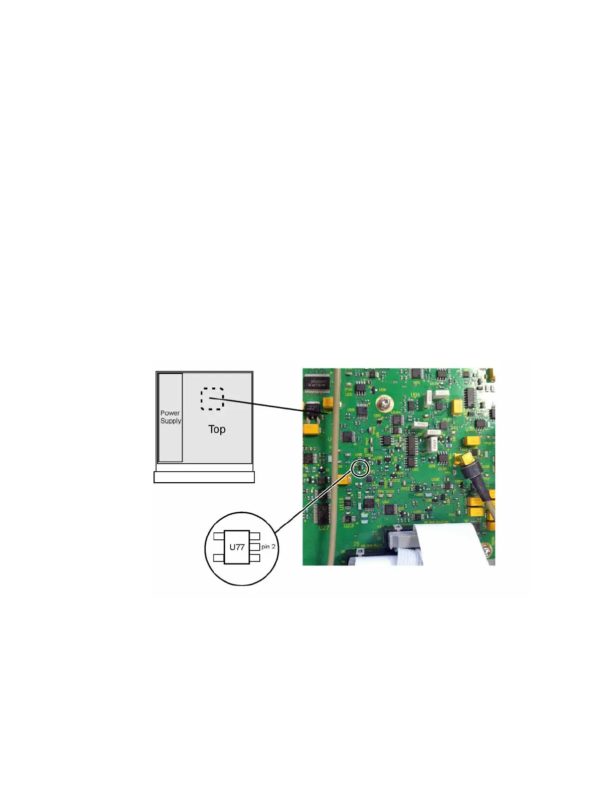
9. Referring to Figure 6-10, connect an oscilloscope to U77 pin 2 on the
A7A1 Microwave ALC Control board assembly.
Figure 6-10 Pulse Modulation Drive Location – A7A1 U77 Pin 2
10.Setup the oscilloscope as follows:
— Amplitude scale = 500 mv/div
— Horizontal scale = 2 µs/div
11.A signal like that shown in Figure 6-11 should be seen on the oscilloscope
screen.
 Loading...


