34 2000/3000 X-Series Oscilloscopes Service Guide
2 Testing Performance
9 Wait until the measurement settles.
10 Read the “current” average voltage value again as V2.
11 Calculate the difference V2 - V1.
The difference in average voltage readings should be within the test limits of
Table 8 or Table 9 (depending on the oscilloscope model).
If a result is not within the test limits, go to the “Troubleshooting” chapter. Then
return here.
12 Disconnect the oscilloscope calibrator from the oscilloscope.
13 Repeat this procedure to check the DC vertical gain accuracy with the
remaining Volts/div setting values in Table 8 or Table 9 (depending on the
oscilloscope model).
14 Finally, repeat this procedure for the remaining channels to be tested.
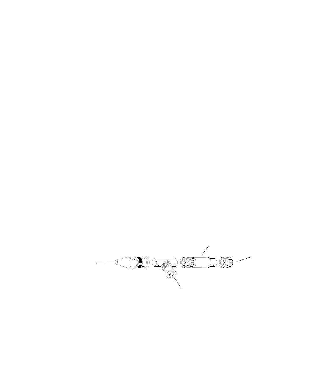
Use a Blocking Capacitor to Reduce Noise
On the more sensitive ranges, such as 1mV/div, 2mV/div, and 5mV/div, noise
may be a factor. To eliminate the noise, add a BNC Tee, blocking capacitor, and
shorting cap at the oscilloscope channel input to shunt the noise to ground. See
Figure 4. If a BNC capacitor is not available, use an SMA blocking capacitor,
adapter, and cap. See “Blocking capacitor and shorting cap in the equipment list
on page 22 for details.
Figure 4 Using a Blocking Capacitor to Reduce Noise
To oscilloscope input
BNC shorting
cap
Blocking
Capacitor

 Loading...


