48 2000/3000 X-Series Oscilloscopes Service Guide
2 Testing Performance
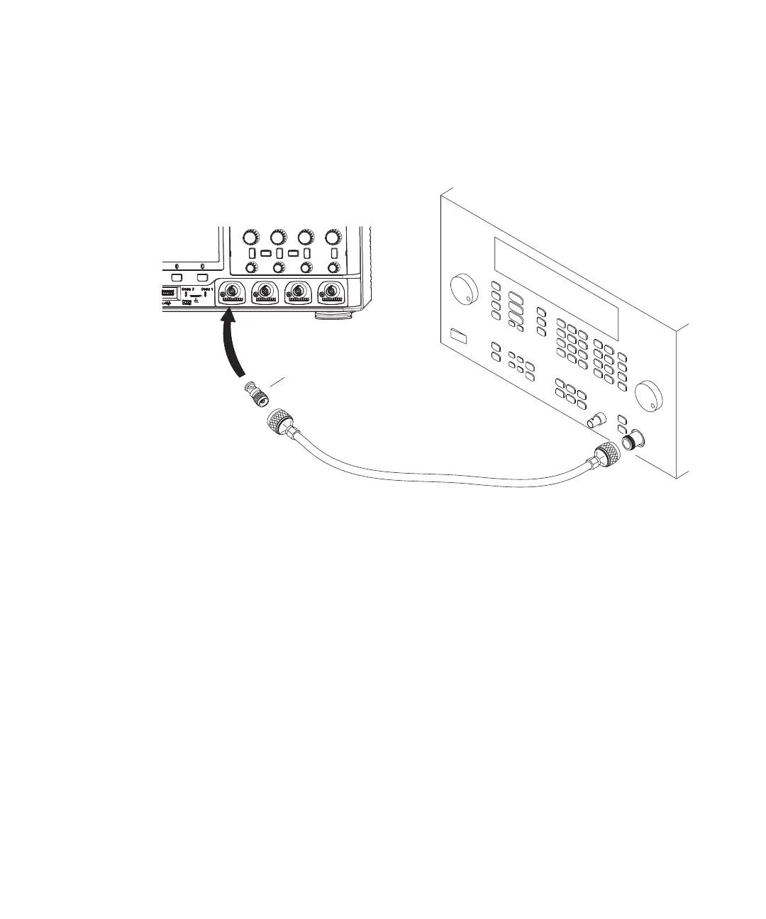
3 Connect the equipment (see Figure 8).
a Connect the signal generator output to the oscilloscope channel 1 input.
Figure 8 Setting Up Equipment for Internal Trigger Sensitivity Test
b With 2000 X-Series oscilloscopes, connect a 50 ohm feedthrough
termination between the channel 1 input and the BNC cable.
With 3000 X-Series oscilloscopes, set channel 1 Imped to 50 Ohm.
4 To verify the trigger sensitivity at the oscilloscope’s maximum bandwidth, set
the output frequency of the signal generator to the maximum bandwidth of the
oscilloscope:
• 1GHz models: 1GHz.
• 500 MHz models: 500 MHz.
• 350 MHz models: 350 MHz.
• 200 MHz models: 200 MHz.
• 100 MHz models: 100 MHz.
• 70 MHz models: 70 MHz.
Signal
Generator
Oscilloscope
N Cable
N to BNC Adapter

 Loading...


