40 Keysight P937xA PXIe Service Guide
Tests, Adjustments, and Troubleshooting
System Verification
3-
System Verification Procedure
1. If you want printed test outputs, connect a printer to the embedded or
remote controller. For the printer, ensure that the correct driver is loaded
and the printer is defined as the default printer. Refer to the network
analyzer’s Help system for information on printer setup.
2. Let the analyzer warm up for at least 15 minutes.
3. Insert the verification kit memory stick in a USB port of the embedded or
remote controller.
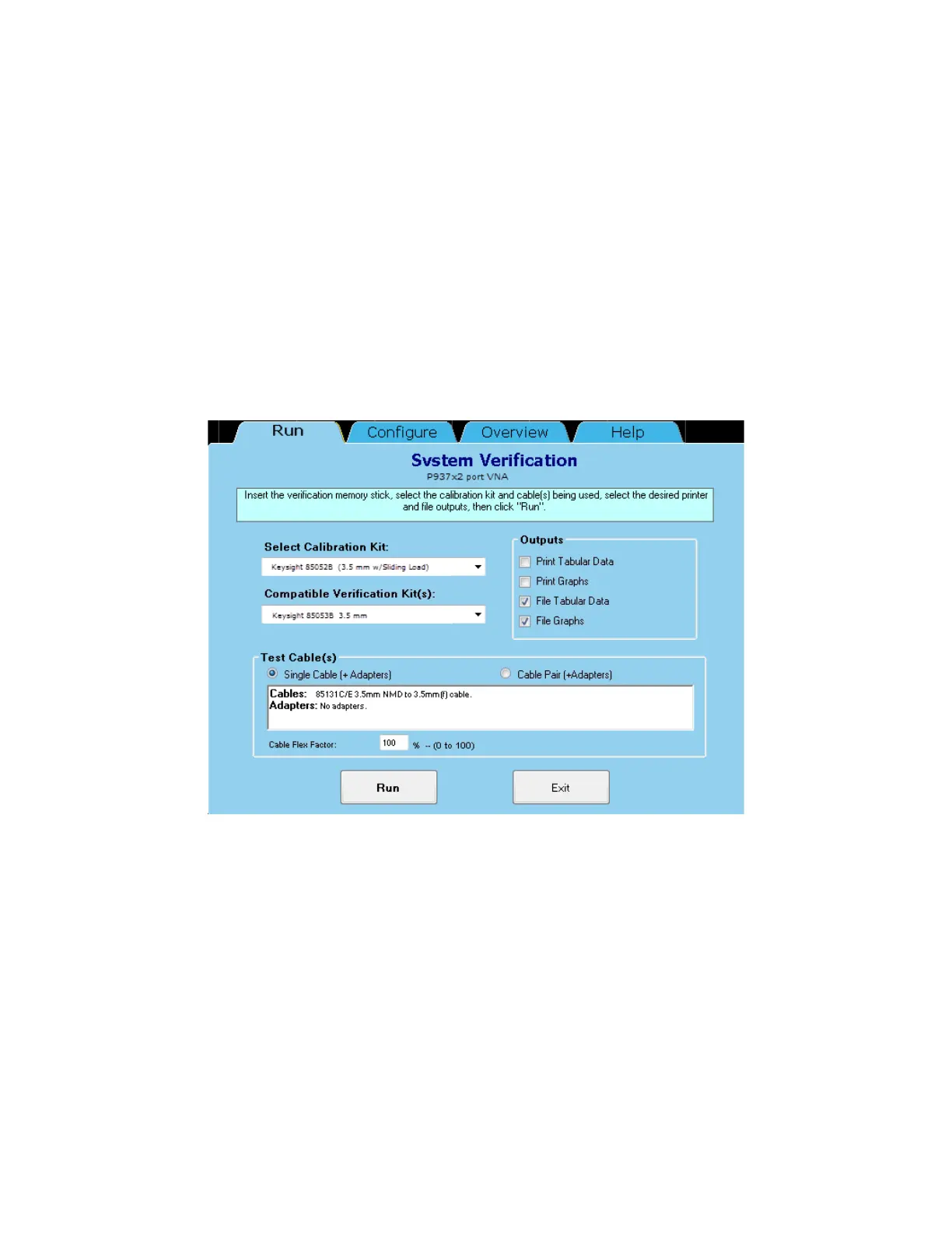
4. Click Utility > System > Service > System Verification. The System
Verification dialog box is displayed, as shown in Figure 3-5.
Figure 3-5 System Verification Dialog Box
5. In the Select Calibration Kit box, click on the calibration kit or electronic
calibration module (ECal) being used. The corresponding verification kit to
use is selected for you and displayed in the Compatible Verification Kit(s)
box.
6. Under Outputs, click one of the following options. Refer to Figure 3-5.
—Print Tabular Data: Prints the verification data in tabular form which
includes measured data and uncertainty limits. For an example, refer
to Figure 3-7 on page 43.
—Print Graphs: Prints the verification data in graphical form. The
graphical form includes measured data trace, factory supplied data
trace, and uncertainty limits. For an example, refer to Figure 3-8 on
page 44.
 Loading...


