PLZ-5W User’s Manual 143
Appendix
Methods to Stabilize Operation
Using the PLZ-5W with fast response speed may cause instable oscillation or other operation instability.
To achieve stabilization, the load cable inductance must be reduced and an appropriate response speed
must be set.
Reducing the load cable inductance
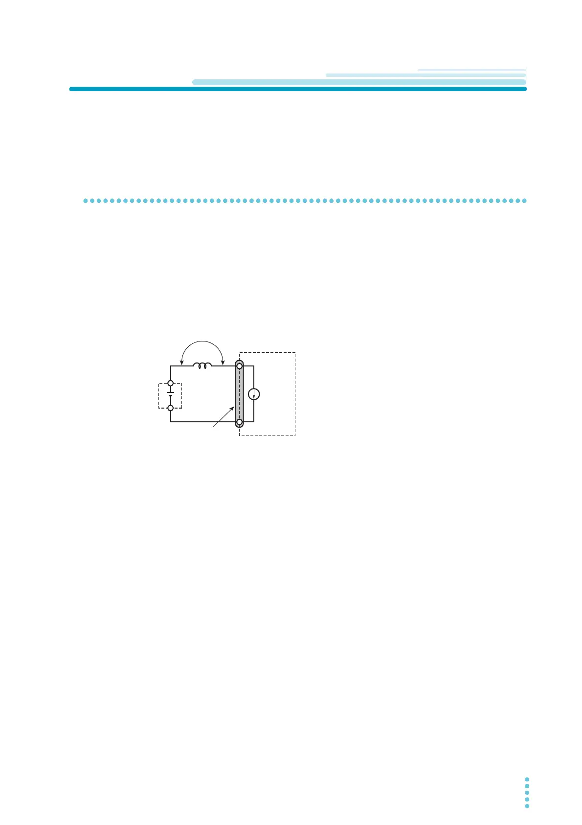
Relationship between voltage induction when current is changed and induc-
tance
Load cables have inductance L. If current I changes quickly, a large voltage is induced on both ends of the
installed cables. If the impedance of the DUT is small, this voltage is entirely applied to the load input ter-
minals of the electronic load. The load cable’s inductance L and voltage E that is induced according to the
changes in current I (hereafter referred to as the induced voltage) are expressed by the following expres-
sion:
Generally, a cable's inductance is 1 μH per meter of cable. If 1 meter of cable (cumulative length of posi-
tive (+) polarity cable and negative (-) polarity cable) is used as the load cable between the DUT and elec-
tronic load, and the current change is 50 A/μs, the induced voltage is 50 V.
The negative (-) polarity of the load input terminals is the reference potential of the external control signal.
Devices connected to external control terminals may malfunction due to the induced voltage.
In constant voltage mode, constant resistance mode, and constant power mode, the load current is varied
by the voltage at the load input terminals. This causes the operation to be easily affected by induced volt-
age.
+
-
E=L (ΔI/ΔT)
E Induced voltage
Wiring inductance
Change in current
Duration of time over which the current changes
L