PLZ-5W User’s Manual 97
External Control | Load Setting Control
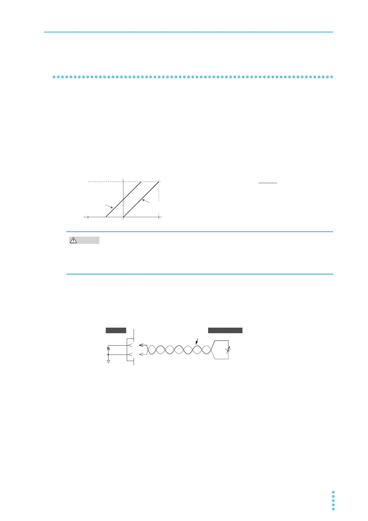
Controlling the current to be superimposed on the constant
current (CC)
You can control the current to be superimposed to the current value of CC mode with an external voltage.
When you apply an external voltage between 0 V to 10 V to the EXT CONT connector, the load current
becomes the sum of the current proportional to the external voltage change and the Present current set-
ting.
When you apply an external voltage between -10 V to 0 V to the EXT CONT connector, the load current is
equal to the current that is proportional to the external voltage change subtracted from the present current
setting.
The current that is added to the current setting for an external voltage of 0 V is 0 A. The current that is
added to the current setting for an external voltage of ±10 V is 100 % of the rating. However, the final load
current range is 0 A to 100 % of the range rating.
1
Turn the POWER switch off.
2
Connect an external voltage across pins 19 and 20 of the EXT CONT connector.
To prevent noise interference, use twisted wires for the signal cables. Use a highly stable external
voltage that has low noise.
3
Turn the POWER switch on and check that the load is off.
4
Sets the operation mode to CC mode, and set the current range.
If you also want to control the current range externally, be sure to set the range to H.
5
Press SOURCE and then More.
6
Use the rotary knob to select CC Add under External Control, and then press Edit.
7
Use the rotary knob to select Enable, and then press ENTER.
External control of superimposing in CC mode is now possible. If Disable is selected, external con-
trol of superimposing in CC mode is disabled. This completes the setting.
Io: Load current
Im: Rated current
Is: Current setting
Ein: External voltage
0A
When the current
setting is 0 A
When the current
setting is Is
Io 㲈 + Is
Im × Ein
10
í V Ein 10 V
0A
Io Im
To avoid damaging the product, observe the following precautions.
• Do not apply a voltage outside ±11 V across pins 19 and 20 of the EXT CONT connector.
• Pin 19 of the EXT CONT connector is connected to the negative (-) load input terminal.
Make sure that the wire of pin 19 does not touch any of the other pins.
20
19
+
–
A COM
EXT CONT ADD
10 kȍ
Twist
EXT CONT
PLZ-5W
External voltage
 Loading...