Page 7
5.a.2 - Output diagnostics
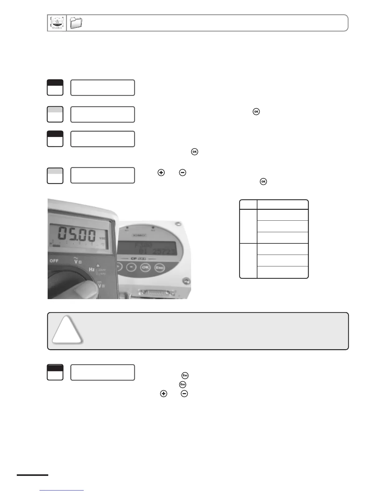
Once the connection of the transmitter to the multimeter (or regulator or PLC/BMS is complete, (see page
6), you can carry out the analogue output diagnostics on several check points.
5. Analogue output management
1
> F 100
Step
Go into configuration mode (see page 2). The folder number displayed
corresponds to the last configuration folder used.
2
> F 300
Step
Select the folder “300” and validate with .
00
3
F 300
Step
Select sub-folder “300”
>
4
Step
04
F 300
>
Channel n° 1 output
and validate with .
The cursor > goes to available choices..
Select sub-folder “303”
Channel n° 2 output
Diagnostic output
00 0 V
01 5 V
02 10 V
03 4 mA
04 12 mA
05 20 mA
F300
!
If the deviations are too large(>0,05V or >0,05mA) between the signal issued and the
value displayed on the multimeter, we recommend that you return the transmitter to
our factory.
04
5
F 300
The cursor > returns to sub-folders line.
• press twice to return to reading mode.
• press once to return to another folder selection.
• with and keys to choose another sub-folder from the folder 300.
>
With and keys, select the signal that the transmitter must output (see
chart below). Note : no need to validate with .
Class 200 transmitter configuration via keypad
Step