Page 6
5. Analogue output management
F300
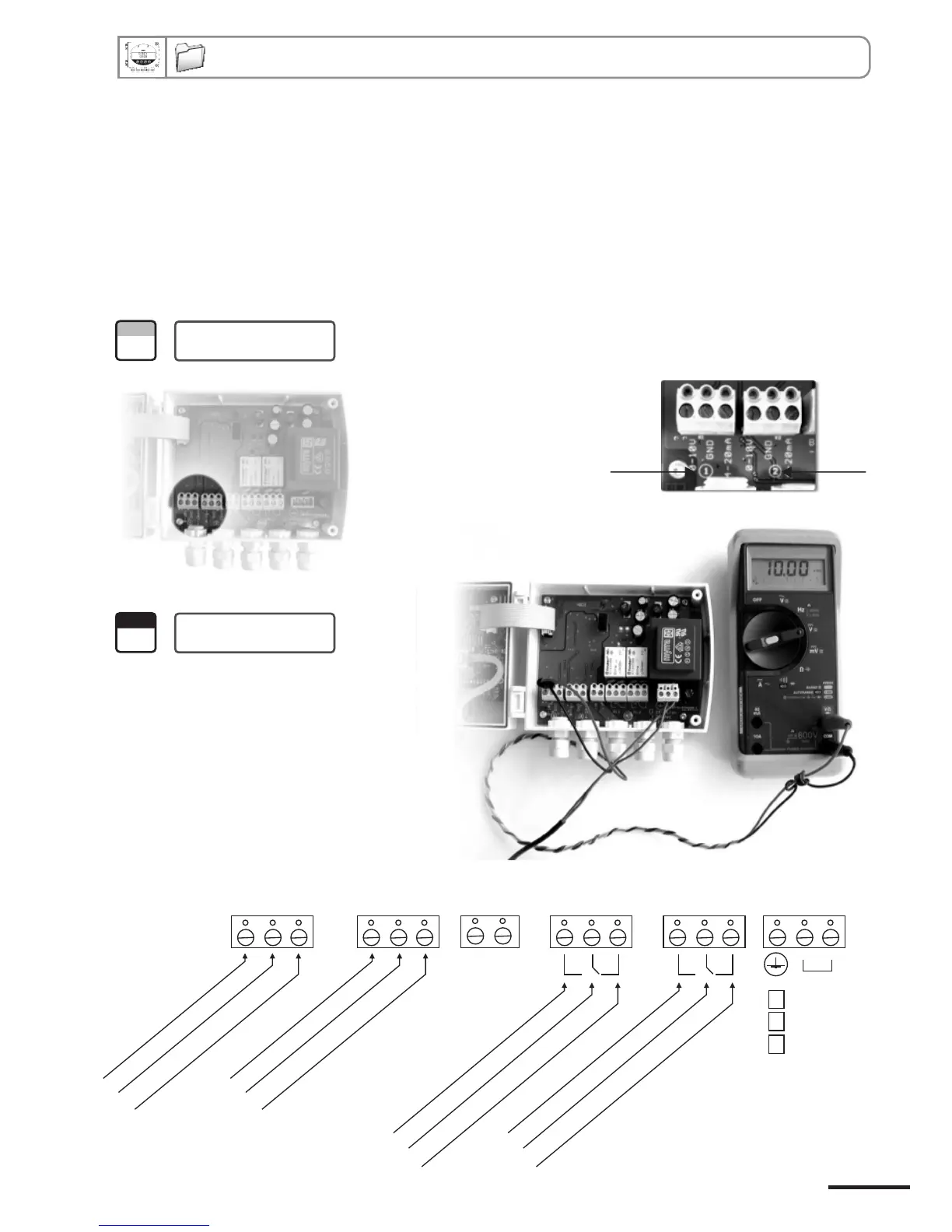
5.a - Output diagnostics
With this function, you can check with a multimeter (or a regulator/display, or a PLC/BMS) if the transmitter outputs
are working properly. The transmitter generates a voltage of 0 V, 5 V and 10 V or a current of 4 mA, 12 mA and
20 mA.
5.a.1 - Multimeter connection configuration
Before carrying out the output diagnostics, all connections and configurations of the transmitter must be
enabled, to avoid any damage on the transmitter and the multimeter !
1
Step
First, select a channel for the output diagnostics.
Selection of the channel
to be checked
The channel numbers are indicated on the
board located below the terminal block.
Channel n°1 Channel n°2
2
Step
Example of
connection
On the photo alongside, the multimeter is
connected to the 0-10 V output and channel
n°1.
NO .............
normally open
COM ..........
common
NC .............
normally closed
Relay 1
NO
.............
normally open
COM
..........
common
NC .............
normally closed
Relay 2
B
-
A
+
0-10 V
..............voltage
GND
.................ground
4-20 mA ...........current
Analogue output 1
0-10 V
..............voltage
GND
.................ground
4-20 mA ...........current
Analogue output 2
The ticked box show
the power supply
type of the transmitter
(230 Vac shown above).
230 Vac
115 Vac
[
24 Vdc / ac
Class 200 transmitter configuration via keypad