12
Disassembly procedure (continued)
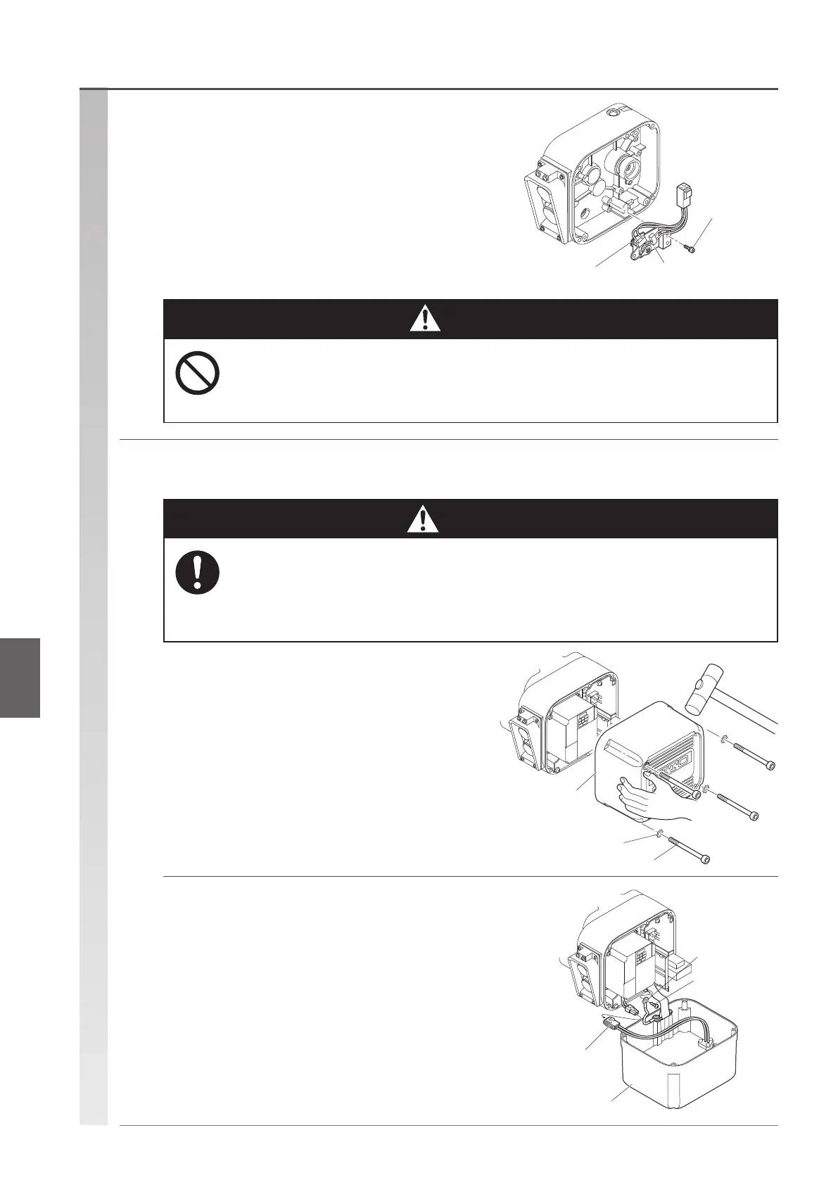
Dual speed inverter type (Basic main body D/E/F type)
Socket bolt
Limit switch
O ring
Controller cover
Socket bolt
Toothed lock washer
Controller cover
Ground line
Pan-head
machine screw
Braking resistor
lead wire
(5) Remove the limit switch as required.
•
Remove the connector of the limit switch rst.
•
Remove it carefully by holding the connector of the limit
switch side.
•
Loosen the 3 socket bolts to remove the limit switch
(replace the O ring attached to the shaft with a new part
upon reassembly).
•
Be careful when removing the limit switch because it may
be damaged if handled in a wrong way.
• Do not disassemble the limit switch.
Replace the limit switch as an assembly. Disassembly causes a defective operation, and a
major accident may occur.
(1) Loosen the 4 socket bolts and open the
controller cover.
•
If it is difcult to open, hit the cover side gently with a
plastic hammer, as shown to the right.
• When opening the controller cover, support it with your hand and open it slowly and carefully.
Failure to follow this instruction may cause the controller cover to hit the internal
electrical components, resulting in damage.
• The controller cover is very hot immediately after operation. Wait until about 30 minutes after
operation.
(2) Remove the connector and ground line
connected to the controller cover.
Prohibited
Mandatory
Disassembly procedureRemoving the controller cover
Danger
Caution
 Loading...