29
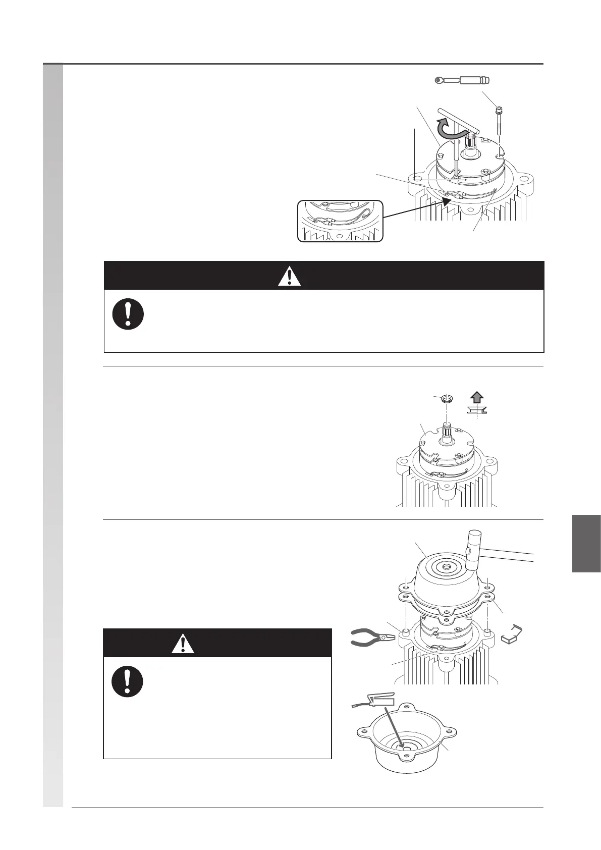
(9) Install the V ring.
•
Insert the V ring to the motor (pinion) shaft.
•
Insert the V ring in the orientation as shown in the gure
until it touches the groove of the motor shaft.
Brake
V ring
Cross-sectional shape
Brake cover side
Brake
(Disassembly
is prohibited.)
Connect the
bullet terminal
after installation
is complete.
Electromagnetic brake gap
Align orientation to the position in the note.
If the lead wire is long
Tighten with
(three) bolts
Torqu e
(8) Install the electromagnetic brake with the
3 socket bolts.
•
Check the orientation of the electromagnetic brake.
Refer to the position data recorded upon disassembly.
•
Check that the lead wire is not too long or too short for
connection.
•
Perform wire connection properly by referring to the
gure.
Tightening torque M6 : 10.8 N·m
M8 : 37.2 N·m
Spring lock washer : Yes
(10) Install the set pin, and then install the brake
cover.
•
The center hole will slide against the V ring, so make sure
to apply Molytherm No.2.
Molytherm No.2 : Several grams
Set pin
Brake cover
Packing B
NEW
Lead wire
Grease
Brake cover
(Apply Molytherm No.2
on the contact face
with the V ring before
installing.)
• Make sure the lead wire is along the side of the brake.
If the lead wire is long, be sure to fold it as shown in the figure.
There is a risk that the lead wire enters the gap of the brake and touches the inside to
cause damage.
Mandatory
Caution
• Check that there is no slack in the lead
wire, and attach the cover while holding
the lead wire so as not to pinch it.
There is a risk that the lead wire enters
the gap of the brake and touches the
inside to cause damage.
Mandatory
Caution
Reassembly procedure
(To be continued)
Assembling the motor and electromagnetic brake
 Loading...