BAC-1xx63/1xxx63 Series (6 Relays and 3 Analog Outputs) Section 36 Application Guide L
• ADVANCED—When the seings are properly congured, this con-
guration complies with CA Title 24, Section 121(c) and ASHRAE
Standard 62.1-2010 and follows guidelines by Portland Energy
Conservation, Inc. (PECI). Although Advanced DCV is the most
complex to congure, it is more energy ecient than Standard while
still optimizing IAQ.
NOTE: See the FlexStat Operation Guide for more information about
conguring DCV.
DCV—Basic Configuration
CO
2
Setpoint
0%
Space CO
2
CO
2
Maximum
DCV Signal
Component
to OAD
100%
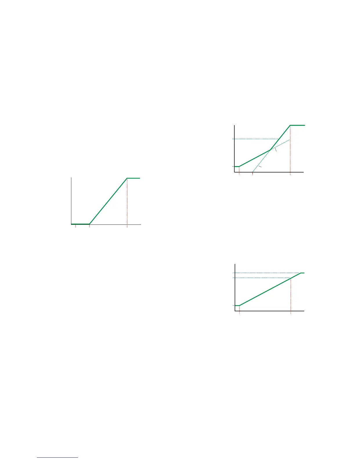
Basic DCV Configuration
CO
2
Base
Outside Air
Damper
Position
Component
During occupied mode, the OA damper opens to Min Position. Upon
Space CO2 rising above CO2 Setpt (600 ppm default), the damper begins
to modulate open from Min Position. The damper modulates fully open
as Space CO2 rises to CO2 Max (1000 ppm default).
NOTE: The three DCV Conguration graphs show the DCV
component of the signal to the outside air damper. Depending
on the conditions and the DCV conguration, the signal to the
damper might be controlled by Minimum Position, Economizer
Loop, or other components. The maximum of these component
values is used, not the sum of them. (If there is a Low Limit
alarm, however, these signals are overridden, and the damper
is closed.)
DCV—Standard Configuration
CO
2
Setpoint
OA Full
OA Area
0%
Space CO
2
CO
2
Maximum
DCV Signal
Component
to OAD
100%
Standard DCV Configuration
CO
2
Base
Outside Air
Damper
Position
Component
“Basic” Signal
“Standard”
Signal
During occupied mode, the OA damper opens to Min Position. Similar
to Basic DCV mode, Standard DCV mode has a PID loop that increases
its output as Space CO2 rises from CO2 Setpt to CO2 Max. Standard
DCV mode also has two additional seings, OA Area (2% default) and
OA Full (5% default). As Space CO2 rises from CO2 Base to CO2 Max,
an internal value is calculated rising proportionally from OA Area to
OA Full. At any point in time during occupied mode, the OA damper is
open the greater of Min Position, the CO2 Setpt loop, or the internally
calculated OA position.
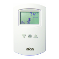
DCV—Advanced Configuration
OA Max
OA Full
OA Area
0%
Space CO
2
CO
2
Maximum
DCV Signal
Component
to OAD*
100%
Advanced DCV Configuration
CO
2
Base
Outside Air
Damper
Position
Component
*Under Normal
Vent Mode operation
(see Vent Mode description)