FlexStat (General) 7 Application Guide, Rev L
Configuration Screens
MAINMENU
ABOUT
ADVANCED
ALARM
DATE/TIME
SCHEDULE
SETPOINTS
SYSTEM
Navigate the menus and change seings by pressing a combination of
buons. Press the:
• Enter buon to select and/or exit value editing.
• Up/Down buon to move among entries (up/down lines).
• Le/Right buon to move among value elds (le/right spaces).
• Le buon to return to the Home screen.
NOTE: A log-in may be required to access menu items.
When prompted about a change (on any menu), press Right/Le to
select the desired choice and then Enter.
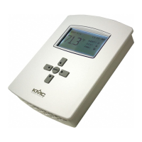
SETPOINTS
COOLSETPT:
HEATSETPT:67°F
COOLSETBACK:80°F
HEATSETBACK:64°F
74°F
SAVECHANGE?
NO
YES
NOTE: If appear at the top of the screen (such as in the Main
Menu), scroll up or down to see the rest of the menu’s o-
screen choices.
See the FlexStat Operation Guide for more conguration and
operation details.
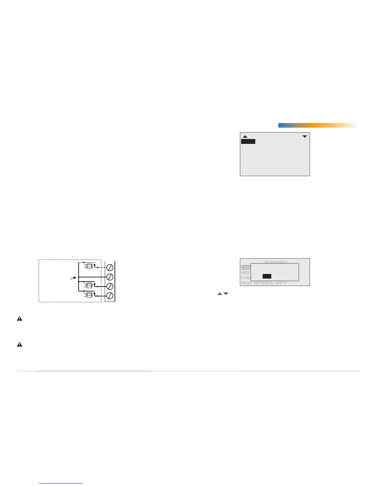
Relay 3 (or 6/9)
SC 1–3 (or 4–6/7–9)
Relay 2 (or 5/8)
Relay 1 (or 4/7)
One Switched
Common
Connection
Per Bank of
Three
Normally
Open Relays
CAUTION
Do not mistakenly connect 24 VAC to an analog output ground.
This is not the same as a relay’s switched common. See the
backplate’s terminal label for the correct terminal.
CAUTION
Relays are for Class-2 voltages (24 VAC) only. Do not connect line
voltage to the relays!
Connect the device under control between the desired output terminal
and the related SC (Switched Common for relays) or GND (Ground
for analog outputs) terminal. For each bank of three relays, there is one
Switched (relay) Common connection (in place of the GND terminal used
with analog outputs).
Do not aach a device that draws current exceeding the FlexStat’s
output capacity:
• Maximum output current for individual ANALOG outputs is 20
mA @ 12 VDC (each).
• Max. output current is 1 A for individual RELAYS @ 24 VAC/VDC
or a total of 1.5 A per bank of 3 relays (relays 1–3 or 4–6).
For example, KMC REE-3111/3112 relays could be connected to the
analog outputs, but REE-3211/3221/3213 relays would exceed the Flex-
Stat’s analog output capacity (although the REE-3211 can be used with
the FlexStat’s internal relays).
FlexStat internal relays are NO, SPST (Form “A”). (To emulate binary
outputs with the analog outputs, set the output voltage to be either 0 or
12 VDC in Control Basic.)
Connecting Outputs
Switched (Relay) Common and Relays