Back-to-Back Desks
STEPS:
1. Attach cradles (A) to legs, (4) per leg, using (2)
¼-20 x 1" machine screws (E) per cradle (A).
2. Attach (2) pairs of starter rails to cradles in
first end leg by first fastening (2) cradle clamp
brackets (B) loosely to each cradle using (4)
¼-20 x
5
/
8
" machine screws (F). Slide one end of
each starter rail into a cradle/clamp assembly,
with rail paint holes facing up and toward the
center of the desk assembly. If glass tops
are being used, holes are to face down and
toward the center of the table desk assembly.
NOTE: Starter rails are typically 3" shorter than
top width. i.e.: 72" wide tops use 69" wide rails.
3. For a two position back-to-back application,
install (8) end caps into the ends of the rails with
a rubber mallet, then slide the other ends of
the rails into the other desk end leg assembly.
For linked applications greater than
two positions, install (4) end caps into
the ends of the starter rails that are
not being linked to the next desk.
4. Position the outer edge of each cradle (A) 4"
from the ends of the rails. Use install gauge to
help properly position leg. See Install Gauge
Guidelines. Tighten the screws (F) in the
cradle clamp brackets (B). For two position
back-to back applications skip step 5.
5. If applicable (for installation of back-to-back
desks with greater than two positions), attach
the ends of the rails without end caps to
another end leg cradle/clamp assembly. Then,
slide extended rails into this assembly. Starter
rails and extended rails should meet in the
center of the cradle. Adjust the leg assembly
position accordingly until this alignment is
met. (See Linked Desk section for starter
rail/ extended rail cradle alignment detail).
Repeat step 5 for all desktop positions, using
install gauge to properly position outermost
legs. See Install Gauge Guidelines.
NOTE: Extended rails are typically
the same length as a desk top. i.e.:
72" wide tops use 72" wide rails.
NOTE: Horizontal rail cradles (A) mounted
to starter rails will be oriented to face
each other. Any additional horizontal rail
cradles (A) mounted to extended rails will
be oriented to face the starter rails. See
the Back-to-Back Linked Desks Plan View
(Four Position) diagram that follows.
Install end caps into the ends of the last pair of
extended rails with a rubber mallet. Tighten the
screws (F) in the cradle clamp brackets (B).
6. If applicable, attach suspended storage,
returns and/or electrical components at this
time. (see suspended storage, desk with
return and electrical installation instructions)
7. Lay tops on base assembly. Use install
gauge to properly position tops. See Install
Gauge Guidelines. Attach tops using (2)
#14 x 1" FH wood screws (G) per cradle
(A). For linked applications greater than
two positions, install (2) flat brackets (H) to
each top-to top connection using (4) #14 x
1" FH wood screws (G) per flat bracket.
8. Surfaces 48" wide and greater require a
spacer (C) for additional support. When
necessary, a spacer should be placed between
the top of each rail and the underside of
the top, centered on the width of the top.
Spacers are attached to the top using (1) #12
X ¾" black wood screw (D) per spacer.
9. Adjust glides as needed to level desk assembly.
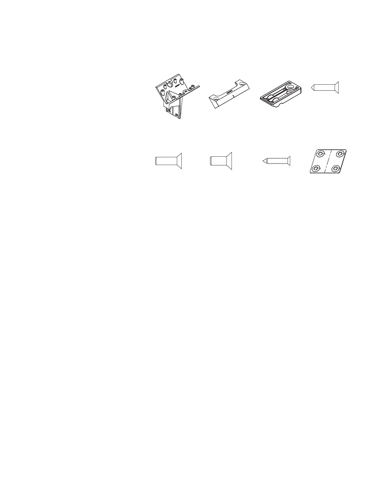
(A) 3AB4004* (B) 3AB4007* (C) 3AB401252
Pattern Numbers Represented:
End Legs for Back to Back Desks (Desk Height), YELD_
Starter Rails with End Caps, YBRS_
Extended Rails (for Step 5 only), YBRE_
Flat Brackets (for Step 5 only), YBF
Parts List:
Horizontal Rail Cradle (A)
Cradle Clamp Bracket (B)
Spacer (C)
#12 X ¾" Black Wood Screw (D)
¼-20 x 1" Machine Screw (E)
¼-20 x
5
/
8
" Machine Screw (F)
#14 x 1" FH Wood Screw (G)
Flat Bracket (H)
End Legs for Back to Back Desks
Rails
End Caps
Tops
Tools Needed:
Drill
Phillips #2 and #3 bits
Rubber Mallet
Install Gauge
(D) 7196440
(E) 7194140 (F) 7189140 (G) 7434100 H.) 3AB4074115