Electrical Requirements
4–6 SITE PREPARATION BEFORE INSTALLATION
Use the following switches:
IMPORTANT
If you cannot use the above manufacturer devices, use an equivalent
emergency switch and contactor in the UL list with the same specifications.
For more information, see UL 2601.1 clause 22.7.
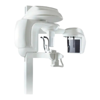
Specifications of the
warning lamps
(5) and (7)
60 W 60 W
• Locate the red warning lamp (5)
outside the x-ray room to indicate
the unit is active (1 lamp at each
access point).
• Locate the green warning lamp (7)
outside the x-ray room to indicate
the ready state of the unit for
acquisition.
Contactor (13) 16A-250V
UL listed
20A-250V
UL listed
Door Safety Switch
(9)
1A / 250V 1A / 130V Optionally, connect the door safety
switch (9) that deactivates the x-ray
remote control if the door remains open.
Emergency Stop Switch:
Manufacturer: Cutler-Hammer
Ref:
• E22AT111
• E22AT112
Contactor:
Manufacturer: Telemecanique
Ref: LC1 D4011
• F6 (110/130 V - 60 Hz)
• P5 (230/240 V - 50 Hz)
• U6 (230/240 V - 60 Hz)
Table 4–2 Electrical Installation Specifications (Continued)
 Loading...