- 32 -
KD 625-2 Workshop Manual_cod. ED0053029380_1° ed_ rev. 00
4
24
26
25
23
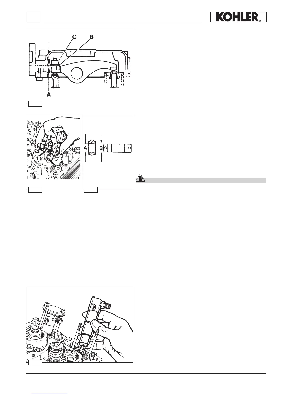
INJECTOR
Clean injector and check calibrated pressure as indicated on page 65.
When retting check that it correctly protrudes from the cylinder head
plane.
Tighten the xing nuts at 10 Nm.
Tighten the high-pressure pipe union at 25 Nm.
Disassembly / Reassembly
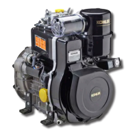
Rocker arm assembly
Components:
1 Bore
2 Lubrication tube
Dimensions (mm):
A = 18.032÷18.050
B = 17.989÷18.000
If clearance (A - B) exceeds 0.135 mm replace shaft and rocker arms.
Caution – Warning
When retitting check that lubrication tube perfectly matches with
the journal bore.
On slow engines, which are set to 1,500 – 1,800 rpm, the rocker arms
differ from the standard version in the upper part of the lubrication
channel.
Tighten the rocker arm shaft fastening screws to the head at a torque
of 25 Nm.
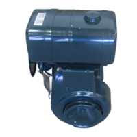
Compression release (optional)
Bring piston to top dead center on the compression stroke.
Unscrew rocker arm cover side plug and measure clearance A between
lever and rocker arm, which must be 0.30÷0.40 mm.
For setting purposes remove the rocker arm cover, unscrew the lock
nut C and set clearance A by changing the height of the shims under
the plate B.
Set the valve/rocker arm clearance, see "Valve / Rocker arm clearance"
on page 31.
Reassemble the rocker arm cover and check the decompression lever
clearance again.
 Loading...