- 48 -
KD 625-2 Workshop Manual_cod. ED0053029380_1° ed_ rev. 00
4
94
95
93
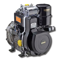
Disassembly / Reassembly
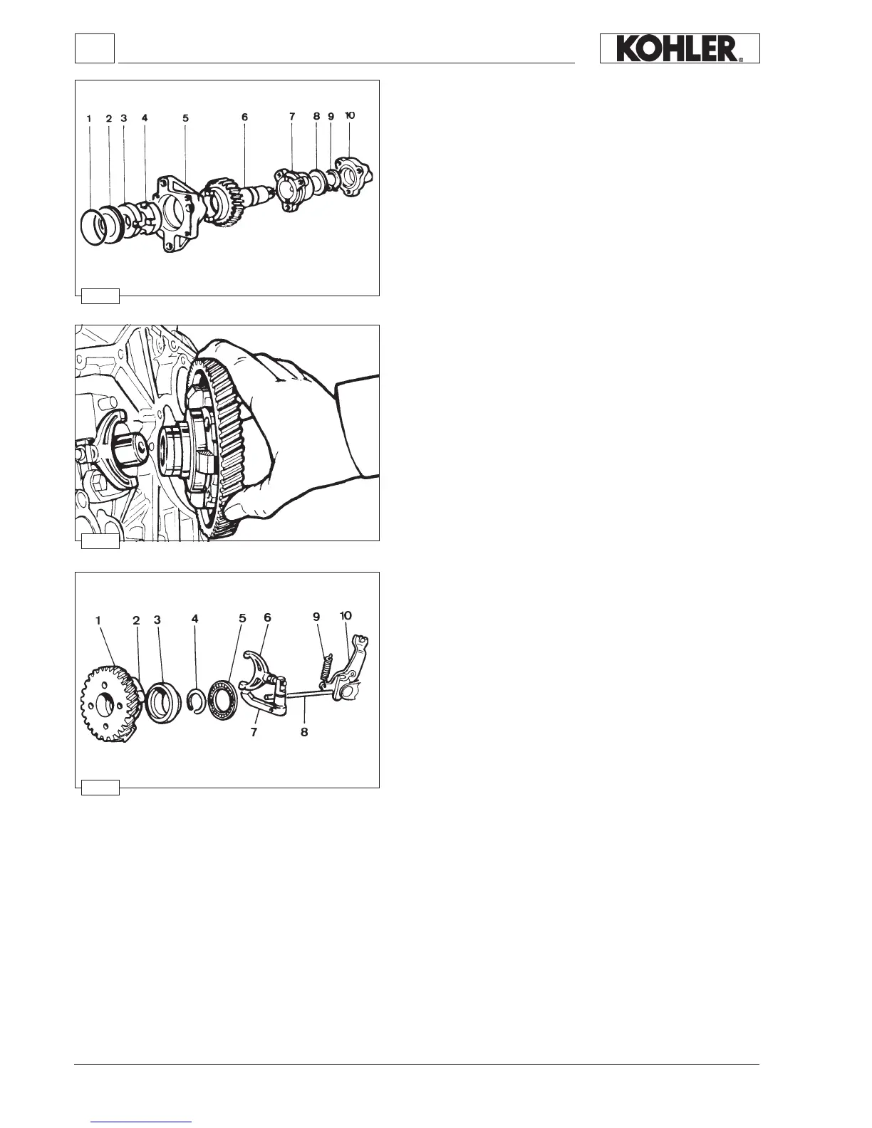
Mechanical speed governor components
1 Gear
2 Weight
3 Mobile bell
4 Stop ring
5 Thrust washer
6 Yoke
7 Lever
8 Drive rod
9 Governor spring
10 Rack control lever
Weights are moved to the periphery by the centrifugal force and thus
axially shift a mobile bell connected to the injection pump rack control
lever by a linkage.
A spring placed under tension by the accelerator control offset the weight
centrifugal force.
Balance between the two forces keeps speed at an almost constant
level in spite of load variations.
See page 62 for timing.
MECHANICAL SPEED GOVERNOR
Weight-type governor housed inside the camshaft drive gear.
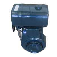
Hydraulic pump components (1 P)
1 Seal ring
2 Centering ring
3 Coupling
4 Half coupling
5 Flange
6 Gear
7 Bracket
8 Thrust washer
9 Stop ring
10 Cover
The maximum total torque is thus 30 Nm corresponding to 12.5 HP at
3000 r.p.m. Reduction ratio 1:1.
 Loading...