10.2.8 Expansion module -2CAN-
Connector X6 of the SERVOSTAR 6xx is assigned to the signals for the RS232 interface and the
CAN interface. It is therefore not the standard pin assignment for these interfaces, and a special
cable is required to be able to use both interfaces simultaneously.
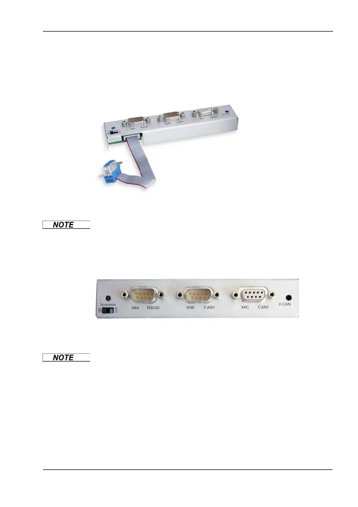
The -2CAN- expansion module provides the interfaces on separate Sub-D connectors. The two
CAN connectors are wired in parallel. A termination resistor (120 W) for the CAN bus can be
switched into circuit if the SERVOSTAR 6xx is at the end of the bus.
10.2.8.1 Installation
The modul must be placed onto the option slot after levering off the cover of the option slot:
l
Screw the distance pieces into the fixing lugs of the option slot.
l
Place the expansion module onto the option slot.
l
Screw the screws into the threads of the distance pieces.
l
Plug the Sub-D9 socket into connector X6 on the SERVOSTAR 600
10.2.8.2 Front View
10.2.8.3 Connection technology
Standard shielded cables can be used for the RS232 and CAN interfaces.
If the servo amplifier is the last device on the CAN bus, then the switch for the bus
termination must be set to ON.
Otherwise, the switch must be set to OFF (condition as delivered).
SERVOSTAR
®
601...620 Instructions Manual 111
Kollmorgen
07/2010 Expansions / Accessories
 Loading...


