6.2.1 Recommended torque
Connector Recommended torque
X3, X4 0.5 to 0.6 Nm (4.43 to 5.31 in lb)
X0A, X0B, X7, X8, X9 0.5 to 0.6 Nm (4.43 to 5.31 in lb)
Ground bolt 3.5 Nm (31 in lb)
6.2.2 Fusing
Internal Fusing
Circuit internal fuse
Auxiliary supply 24V 3.15 AT (FRx-3)
Brake resistor electronic
External fusing
Fusible cutouts or similar
(Fuse UL time delay)
SERVOSTAR
601/ 603
SERVOSTAR
606/ 610
SERVOSTAR
614/ 620
AC supply F
N1/2/3
6 AT (FRx-6) 10 AT (FRx-10) 20 AT (FRx-25)
24V supply F
H1/2/3
max. 12 AF (max. FRx-12)
Brake resistor F
B1/2
6 AT (FRS-6) 10 AT (FRS-10) 10 AT (FR10-10)
(x=SorS-Rfor480V applications x=NorN-Rfor230V applications)
6.2.3 Ambient conditions, ventilation, mounting position
Storage, hints
ð p.17
Transport, hints
ð p.17
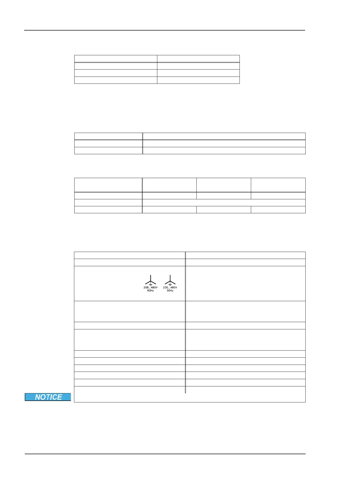
Supply voltage tolerances
Input power
Aux. power supply
min 3x 230V
-10%
AC / max 3x 480V
+10%
,50Hz
min 3x 208V
-10%
AC / max 3x 480V
+10%
,60Hz
24 VDC (-0% +15%), check voltage drop
Ambient temperature in operation
0 to +45°C (32 to 113°F) at rated data
+45 to +55°C (113 to 131°F) with power derating
2.5% / K
Humidity in operation
rel. humidity 85%, no condensation
Site altitude
up to 1000m a.m.s.l. without restriction
1000 — 2500m a.m.s.l. with power derating
1.5%/100m
Pollution level Pollution level 2 to EN 60664-1
Vibrations
Class 3M1 according to IEC 60721-3-3
Noise emission
max. 45 dB(A)
Enclosure protection
IP 20 according to EN60529
Mounting position
generally vertical. ð p.36
Ventilation
forced convection by built-in fan
Make sure that there is sufficient forced ventilation within the switchgear cabinet.
24 SERVOSTAR
®
601...620 Instructions Manual
Technical description
07/2010 Kollmorgen
 Loading...


