Do you have a question about the Kollmorgen SERVOSTAR 614 and is the answer not in the manual?
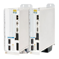
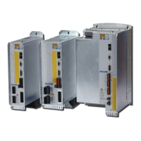
Describes the SERVOSTAR 600 series digital servo amplifiers and related manuals.
Identifies personnel qualifications required for handling, installation, and setup.
Explains safety symbols and their indications in the manual.
Lists and defines abbreviations used throughout the manual.
Provides critical safety warnings regarding electrical hazards and proper handling.
Specifies intended use of servo amplifiers and environmental conditions.
Lists environments and applications where the servo amplifier must not be used.
Details UL and cUL certifications and their requirements for safety.
Covers EC directives (EMC, Low Voltage) and relevant product standards.
Certification for compliance with GOST-R standards.
Guidelines for safe transport, including temperature and humidity.
Information on required maintenance and cleaning procedures.
Steps for safely disassembling the servo amplifier.
Lists items included in the SERVOSTAR 600 amplifier package.
Describes the information found on the servo amplifier's nameplate.
Explains the structure and coding of part numbers for the amplifiers.
Overview of the SERVOSTAR 600 series, including current ratings and widths.
Provides detailed electrical, mechanical, and environmental specifications.
Describes amplifier behavior during power-up, power failure, and stopping.
Explains stop categories and emergency stop functions per EN 60204.
Provides notes on site, ventilation, assembly, grounding, and shielding.
Critical safety warnings for electrical connections and wiring practices.
Step-by-step notes for correct electrical installation procedures.
Details on routing cables, shielding, and connecting various components.
Illustrates connection variations for different mains supply networks.
Overview of supported feedback types and their connection parameters.
Describes the function and connection of digital and analog I/O.
Details on connecting the servo amplifier to a PC via RS232.
Information on connecting the servo amplifier to a CAN bus.
Safety precautions before starting the setup procedure.
Describes installation and use of the DRIVE.EXE setup software.
Provides a simplified procedure for initial setup and testing.
Lists and explains error codes displayed by the amplifier.
Lists and explains warning codes displayed by the amplifier.
Provides guidance on troubleshooting and resolving common faults.
Details the -AS- option for personnel safety and restart prevention.
Guide to installing various expansion cards.
Describes the I/O-14/08 expansion card's features and technical data.
Information on the PROFIBUS expansion card and its connection.
Details the EtherCAT expansion card and its LEDs.
Definitions of technical terms used in the manual.
Lists order codes for servo amplifiers, expansion cards, and accessories.
| Type | Digital Servo Amplifier |
|---|---|
| Number of axes | 1 |
| Control Mode | Position, Velocity, Torque |
| Communication Interface | CANopen, EtherCAT |
| Cooling | Forced air |
| Feedback | Resolver |
| Protection Features | Overcurrent, Overvoltage, Overtemperature |
| Operating Temperature | 0°C to 45°C |
| Storage Temperature | 70 °C |
| Humidity | Up to 95% non-condensing |